Automatic-focusing high-precision large-stroke precision positioning workbench

A precise positioning and auto-focusing technology, applied in manufacturing tools, metal processing equipment, welding equipment, etc., can solve the problems of insufficient focusing speed, difficult to meet precision engineering, and insufficient focusing accuracy, and achieve simple structure and cost. Low, low cost effect

Inactive Publication Date: 2014-05-21
HARBIN INST OF TECH AT WEIHAI
View PDF7 Cites 5 Cited by
  • Summary
  • Abstract
  • Description
  • Claims
  • Application Information

AI Technical Summary

Problems solved by technology

The focusing accuracy of the traditional motion platform is not high enough, and it is easy to cause misfocusing; in many laser processing processes, it is necessary to have a processing positioning accuracy of 0.01um
[0007] Most of the existing technologies have the disadvantage of poor focus stability, and are easily affected by various noises in the environment and hardware; for example, there is an error in the motor that controls the movement of the lens, there is inertia in the movement of the lens, and there is a time delay in the hardware drive, which causes The focusing speed cannot meet the requirements, and even the most advanced technology needs to be improved in intelligence and real-time performance. In the existing technology, it is necessary to collect and compare spot images by computer, which is time-consuming and laborious, and the travel is not enough, so it is difficult to meet the needs of precision engineering; When laser processing workpieces, a vertical stroke of 100mm is required. It is difficult for ordinary precision platforms to meet this requirement, so there is room for improvement.

Method used


Image

  • Automatic-focusing high-precision large-stroke precision positioning workbench
  • Automatic-focusing high-precision large-stroke precision positioning workbench
  • Automatic-focusing high-precision large-stroke precision positioning workbench

Examples


Embodiment Construction

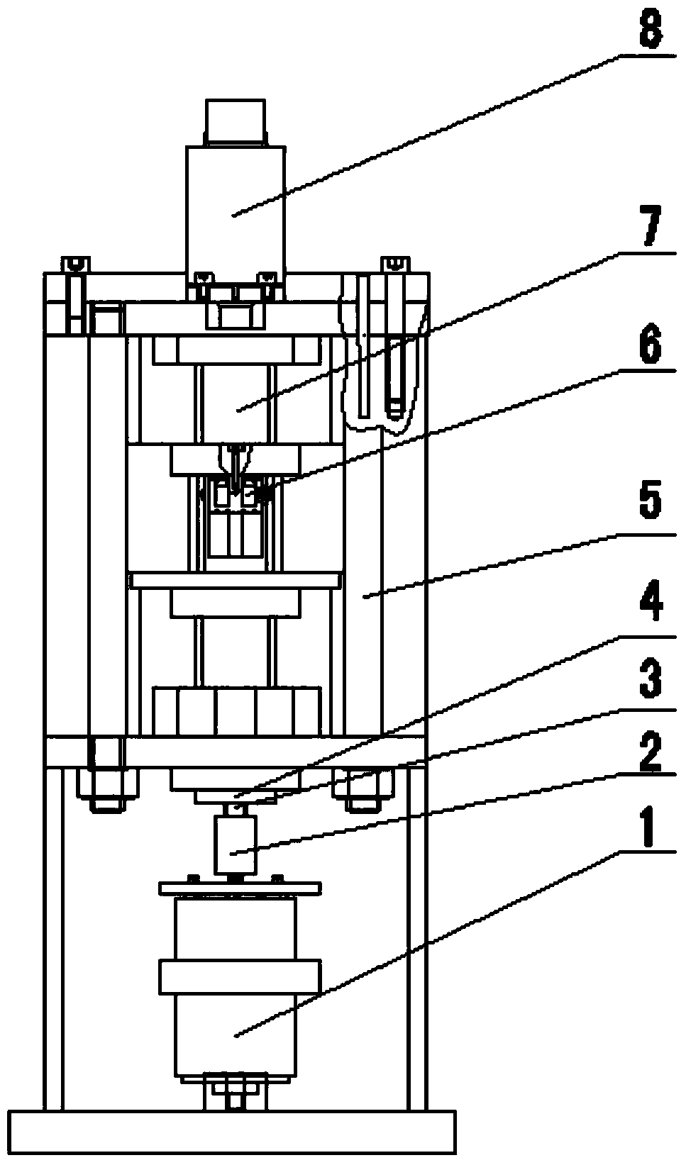
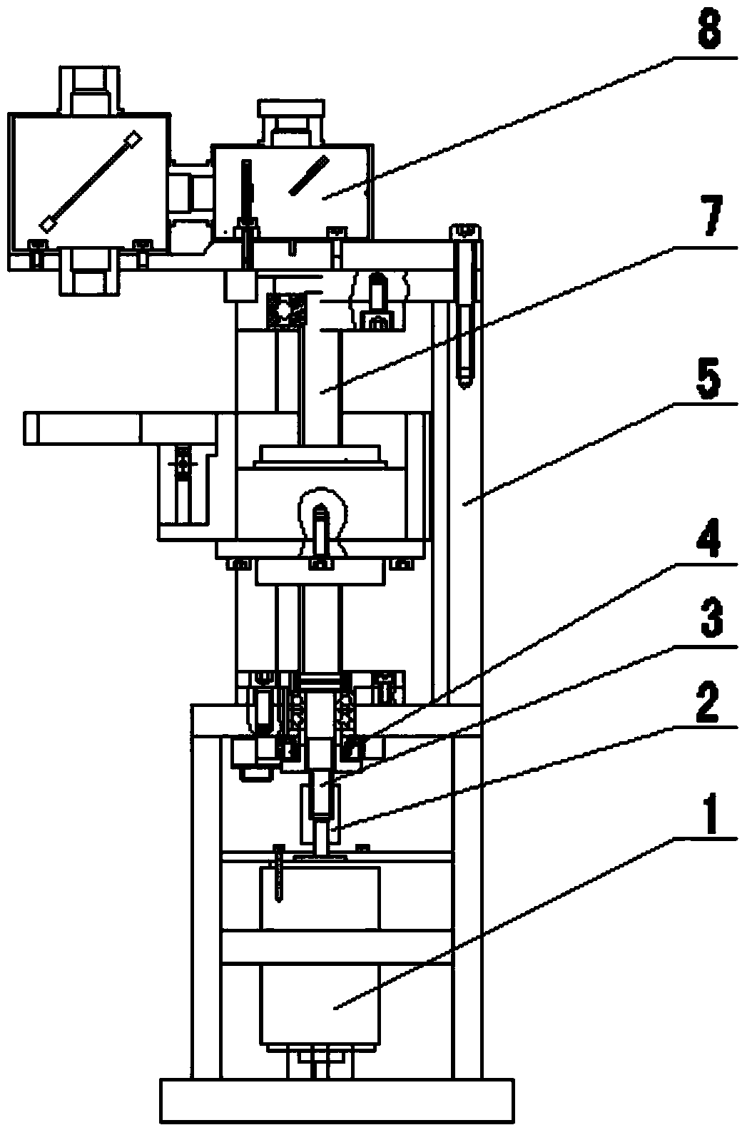
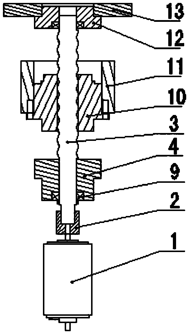
[0021] The present invention will be further described below in conjunction with accompanying drawing:

[0022] Such as Figure 1 to Figure 3 As shown: the present invention includes a motor 1, a high-precision ball screw 3, a high-precision ball screw lower support 4, a support rod 5, piezoelectric ceramics 6, a triangular laser emitting device 8, a high-precision ball screw nut 10, and a high-precision ball screw nut 10. The upper support 12 of the precision ball screw and the platen 13, the rotating shaft of the motor 1 is connected with the lower end of the high-precision ball screw 3 in the vertical upward direction, and the lower support 4 of the high-precision ball screw is set on the bottom of the high-precision ball screw 3 The lower section, the high-precision ball screw nut 10 is set on the middle section of the high-precision ball screw 3, the high-precision ball screw upper support 12 is set on the upper section of the high-precision ball screw 3, and the support ...


PUM


Abstract

The invention discloses an automatic-focusing high-precision large-stroke precision positioning workbench. The automatic-focusing high-precision large-stroke precision positioning workbench comprises a motor, a high-precision ball screw, a high-precision ball screw lower support, a supporting rod, piezoelectric ceramic, a triangular laser emission device, a high-precision ball screw nut, a high-precision ball screw upper support and a platen. Compared with the prior art, the double control scheme is adopted for the automatic-focusing high-precision large-stroke precision positioning workbench in the aspect of an overall mechanical structure, the automatic-focusing high-precision large-stroke precision positioning workbench can have low cost while meeting the requirement for high precision, and meanwhile vibration produced by the direct current motor during driving is avoided. An automatic positioning system used in the automatic-focusing high-precision large-stroke precision positioning workbench is more stable than the prior art, contrast calculation carried out by a computer is not needed, and particularly, the automatic-focusing high-precision large-stroke precision positioning workbench is simple in structure, low in cost, high in rigidity, high in reliability and convenient to use, and has popularization value.

Description

technical field [0001] The invention relates to a precision positioning and focusing device, in particular to an automatic focusing high-precision and large-stroke precision positioning workbench. Background technique [0002] The Tokyo Institute of Technology has developed a one-dimensional linear motor-driven ultra-precision workbench with nanoscale resolution. It is guided by an air-floating guide rail with a stroke of 300mm. The vertical stiffness of the guide rail is 600N / um and the horizontal stiffness is 220N / um. The workbench weighs 19.6kg and is all made of alumina ceramic materials. The linear motor has a driving force of 160N, a maximum acceleration of 6.4m / s2, and a maximum speed of 320mm / s. The feedback measurement system uses a laser interferometer with a resolution of 0.63nm. The control system adopts PID controller with feed-forward compensation. Its biggest feature is that it is equipped with an electrorheological damper, which can actively control the dy...

Claims


Application Information

Patent Timeline
Patent Type & Authority Applications(China)
IPC IPC(8): B23K26/042B23K26/08
CPCB23K26/046B23K26/083
Inventor 李从生王延深冯薇薇雷岩
Owner HARBIN INST OF TECH AT WEIHAI
Why Eureka
Try Eureka