Al technical title is built by PatSnap Al team. It summarizes the technical point description of the patent document.
A thick-film heater and thick-film technology, applied in water heaters, fluid heaters, lighting and heating equipment, etc., can solve problems such as inability to improve cleaning efficiency, inability to realize rapid adjustment of liquid temperature, inability to accurately control liquid temperature, etc. problem, to achieve the effect of short cooling time, short temperature rising time and controllable temperature
Active Publication Date: 2014-05-21
CHANGZHOU RUIZE MICROELECTRONICS
View PDF4 Cites 3 Cited by
Summary
Abstract
Description
Claims
Application Information
AI Technical Summary
This helps you quickly interpret patents by identifying the three key elements:
Problems solved by technology
Method used
Benefits of technology
Problems solved by technology
However, for some semiconductor device cleaning, it is necessary to wash with a relatively low temperature corrosive liquid first, and then use a relatively high temperature corrosive liquid for flushing, and the electric heater with this structure is not suitable
At present, one is cleaned with cleaning liquids of different temperatures through two processes, but there are problems of high cleaning cost and low cleaning efficiency; the other is cleaned by one process, and it is necessary to prolong the pause in the cleaning process due to the different temperatures of the cleaning liquids. Auxiliary time, to reduce the temperature of corrosive liquids
Since the corrosive liquid only depends on the ambient temperature to cool down after stopping heating, on the one hand, it is impossible to quickly adjust the liquid temperature, and on the other hand, it cannot accurately control the liquid temperature, which cannot improve the cleaning efficiency.
Method used
Image
Click on the blue label to locate the original text in one second.
Reading with bidirectional positioning of images and text.
Examples
Embodiment Construction
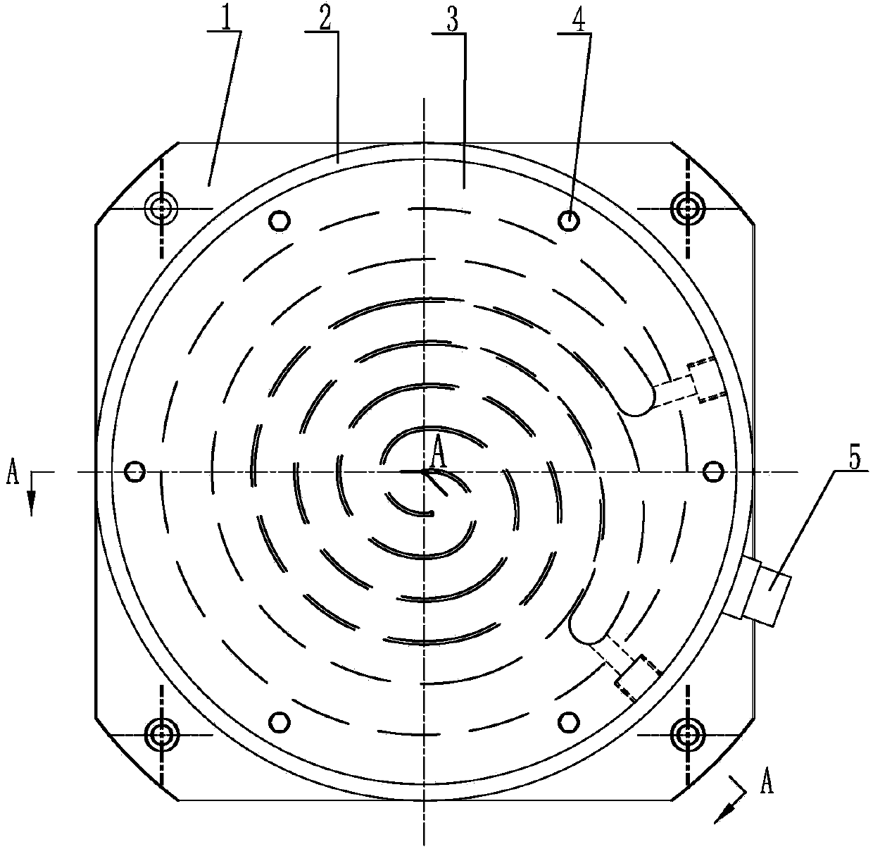
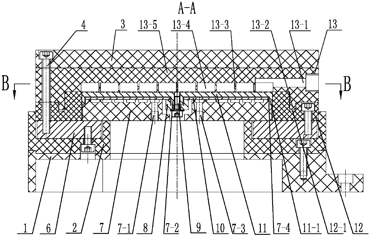
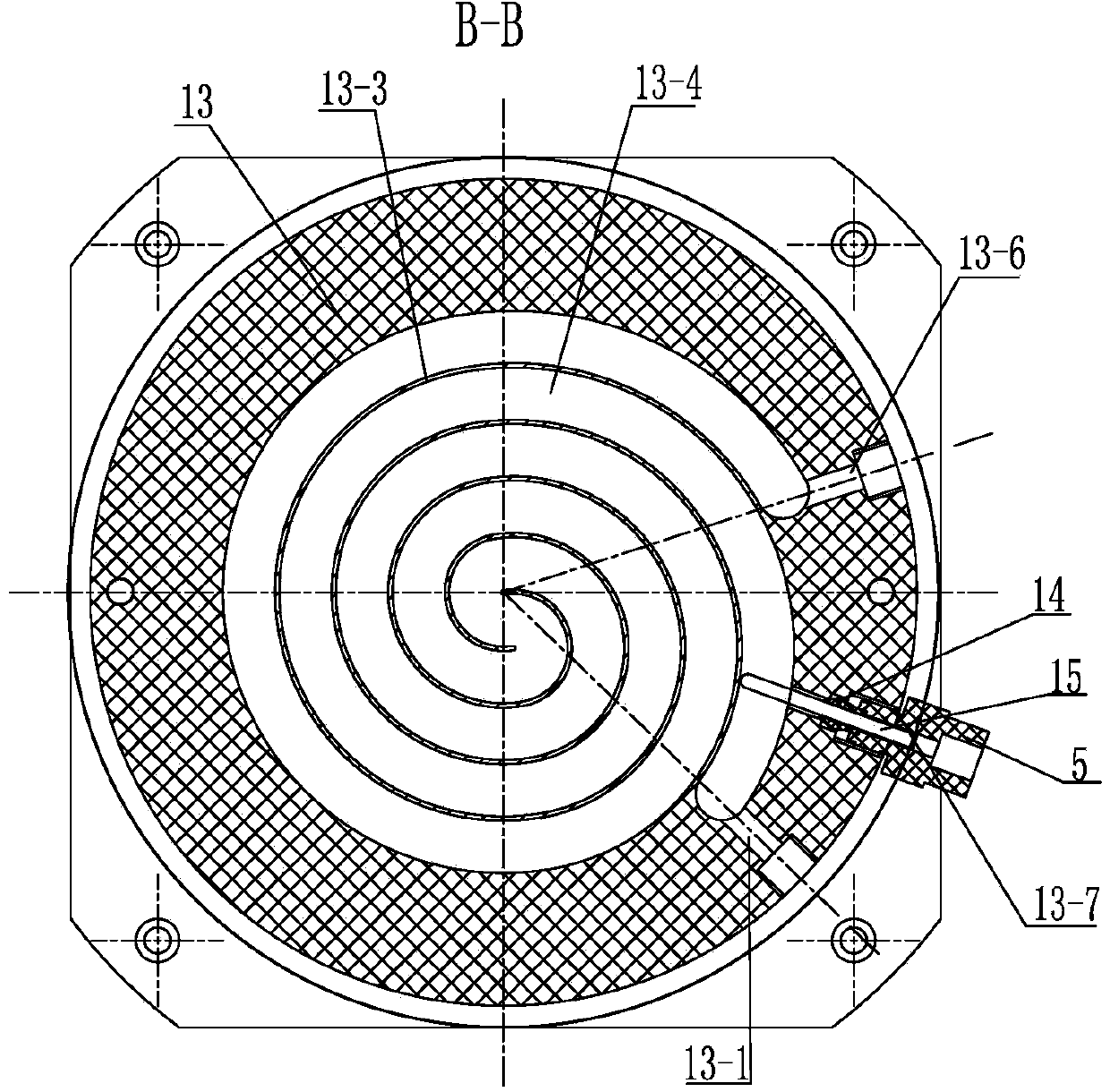
[0020] See Figure 1~3 As shown, the thick film heater of the present invention includes a thick film heating disc 10 , a heating disc press block 7 arranged at the bottom of the thick film heating disc 10 , a heat conduction disc 11 arranged at the upper part of the thick film heating disc 10 and a heating pool 13 . See figure 2 As shown, an air groove is provided on the surface where the heating plate pressing block 7 of the present invention is connected with the thick film heating plate 10, and the air inlet port 7-1 and the air outlet port 7-3 on the heating plate pressing block 7 communicate with the air groove, The air groove on the heating plate pressing block 7 of the present invention rotates outward along the center of the heating plate pressing block 7 and forms a spiral air groove, or the air groove on the heating plate pressing block 7 is a positive plate connecting more than two U-shaped air grooves. Groove, make the air groove on the heating plate pressing bl...
PUM
Abstract
The invention relates to a thick film heater. The thick film heater comprises a thick film heating disk, a heating disk pressing block, a heat conduction disk and a heating pool, wherein the heating disk pressing block is arranged on the lower portion of the thick film heating disk, the heat conduction disk and the heating pool are arranged on the top of the thick film heating disk, a gas groove is formed in the surface, making contact with the thick film heating disk, of the heating disk pressing block, a gas inlet connector and a gas outlet connector formed in the heating disk pressing block are communicated with the gas groove, the heating pool which is made of fluoroplastic or is provided with a fluoroplastic layer is provided with a pool cover and a flow guide plate, the flow guide plate on the heating pool is attached to the heat conduction disk, a cavity of the heating pool is divided by the flow guide plate to form a surrounding liquid flow channel, a liquid inlet connector and a liquid outlet connector are formed in the heating pool, and are communicated with the liquid flow channel, a first temperature sensor which is used for detecting the temperature of outlet liquid is installed on the side, with the liquid outlet connector, of the heating pool, the detection end of the first temperature sensor is arranged in the liquid flow channel, and a second temperature sensor is installed on the heat conduction disk. According to the thick film heater, the temperature of the liquid can be controlled conveniently, rapidly and accurately, operation is reliable, cleaning efficiency is improved, and maintenance is convenient.
Description
technical field [0001] The invention relates to a thick-film heater working in an acid-base environment, belonging to the technical field of liquid heating. Background technique [0002] Corrosive liquids are used in chemical etching and cleaning processes of semiconductor devices, and the cleaning process requires heating of the corrosive liquids. The electric heater used for heating corrosive liquid is to set the electric heating material in the stainless steel sleeve, and the metal magnesium oxide is set between the stainless steel sleeve and the electric heating wire, and the outer wall of the stainless steel sleeve is coated with polytetrafluoroethylene, and the stainless steel sleeve It is installed in the box or cylinder to heat the added corrosive liquid, although the electric heater with this structure has the advantages of corrosion resistance and large heating liquid volume. However, for cleaning some semiconductor devices, it is necessary to wash with a relative...
Claims
Application Information
Patent Timeline
Application Date:The date an application was filed.
Publication Date:The date a patent or application was officially published.
First Publication Date:The earliest publication date of a patent with the same application number.
Issue Date:Publication date of the patent grant document.
PCT Entry Date:The Entry date of PCT National Phase.
Estimated Expiry Date:The statutory expiry date of a patent right according to the Patent Law, and it is the longest term of protection that the patent right can achieve without the termination of the patent right due to other reasons(Term extension factor has been taken into account ).
Invalid Date:Actual expiry date is based on effective date or publication date of legal transaction data of invalid patent.