An oil separator and a compressor and a refrigeration system using the oil separator

An oil separator and refrigeration system technology, applied in the field of compressors, can solve the problems of incomplete oil and gas separation and lack of oil in the compressor, and achieve the effects of shortening the circulation path, reducing wear and improving the energy efficiency of air conditioners.

Inactive Publication Date: 2016-05-18
ZHUHAI LANDA COMPRESSOR +1
View PDF4 Cites 3 Cited by
  • Summary
  • Abstract
  • Description
  • Claims
  • Application Information

AI Technical Summary

Problems solved by technology

[0010] The purpose of the present invention is to provide an oil separator to solve the technical problem of incomplete oil-gas separation and the lack of oil in the compressor produced in the prior art

Method used


Image

  • An oil separator and a compressor and a refrigeration system using the oil separator
  • An oil separator and a compressor and a refrigeration system using the oil separator
  • An oil separator and a compressor and a refrigeration system using the oil separator

Examples


Embodiment 1

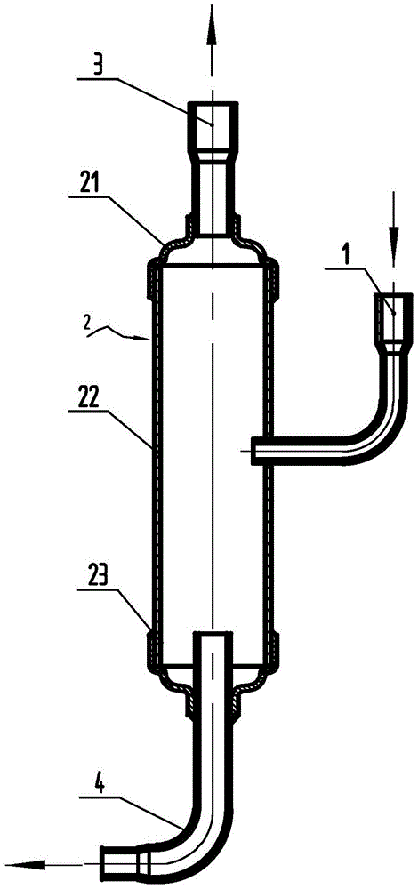
[0039] figure 2 Shown is a first embodiment of the invention, as figure 2 The oil separator 10 shown is used to realize the separation of lubricating oil and refrigerant in the refrigeration system. The refrigeration system includes a compressor and a condenser, and the oil separator is connected between the compressor and the condenser. , the oil separator is a single structure, including cylinder 2, inlet pipe 1, outlet pipe 3 and oil return pipe 4, the inlet pipe 1 is used to connect with the exhaust pipe of the compressor, the outlet The air pipe is used to connect the condenser, and one end of the oil return pipe 4 extends into the barrel 2, and the other end is connected to the compressor oil pool.

[0040] Depend on figure 2 It can be seen that the cylinder 2 is a closed cylinder, the air inlet pipe 1 extends from the middle of the cylinder 2, the air outlet pipe 3 protrudes from the top of the cylinder, and the oil return pipe One end extends into the cylinder bo...

Embodiment 2

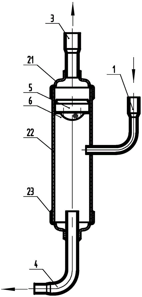
[0045] image 3 Shown is a second embodiment of the invention, as image 3 The oil separator 10 shown is used to realize the separation of lubricating oil and refrigerant in the refrigeration system. The refrigeration system includes a compressor and a condenser, and the oil separator is connected between the compressor and the condenser. , the oil separator is a single structure, including cylinder 2, inlet pipe 1, outlet pipe 3 and oil return pipe 4, the inlet pipe 1 is used to connect with the exhaust pipe of the compressor, the outlet The air pipe is used to connect the condenser, and one end of the oil return pipe 4 extends into the barrel 2, and the other end is connected to the compressor oil pool. The difference from Embodiment 1 is that the oil separator of Embodiment 2 also includes a filter assembly, which is placed inside the cylinder and at the front end of the outlet pipe 3, and the filter assembly includes a filter screen 5 And the filter screen support 6, the...

Embodiment 3

[0048] Figure 4 Shown is the third embodiment of the present invention, the structure of this embodiment is basically the same as the second embodiment, and the difference from the first embodiment is that the filter group of the oil separator of the third embodiment is placed at the front end of the oil return pipe 4, so The filter assembly includes a filter screen 5 and a filter screen support 6, the filter screen support 6 is fixedly connected to the cylinder body 22, the filter screen 5 is covered on the support in an arc shape, and the arc surface of the filter screen is convex upward out. Set the filter screen assembly at the front end of the oil return pipe 4 to prevent impurities from falling into the oil return pipe, and ensure that after the impurities are separated from the oil-air mixture, the returned lubricating oil, especially large particles of impurities, will no longer flow back to the oil pool of the compressor with the refrigerant , which can reduce the w...


PUM


Abstract

The invention relates to an oil separator as well as a compressor and a refrigerating system using the oil separator. The oil separator is connected between the compressor and a condenser and comprises a cylinder, a gas inlet pipe, a gas outlet pipe and an oil return pipe, wherein the gas inlet pipe is connected with an exhaust pipe of the compressor, the gas outlet pipe is connected with the condenser, one end of the oil return pipe extends into the cylinder, and the other end of the oil return pipe is connected with an oil sump of the compressor. According to the technical scheme, the technical problem of compressor oil shortage due to the fact that oil and gases in refrigerants are not separated thoroughly in existing compressors and refrigerating systems is effectively solved.

Description

technical field [0001] The invention relates to the field of compressors, in particular to an oil separator, a compressor and a refrigeration system using the oil separator. Background technique [0002] In the refrigeration system of the prior art, it generally includes components such as a compressor, a condenser, an evaporator, and a capillary tube. The circulation of the refrigerant in the refrigeration system is roughly as follows: [0003] First, the refrigerant is compressed into a high-temperature and high-pressure gas phase in the compressor, and then flows into the condenser. In the condenser, the gaseous refrigerant exchanges heat with the outside air or cooling water to become a liquid refrigerant at room temperature and high pressure. When the high-pressure liquid refrigerant in the condenser flows through the capillary tube, the pressure is reduced to become a cooled refrigerant; the refrigerant becomes a low-pressure liquid and is easy to evaporate. Therefor...

Claims


Application Information

Patent Timeline
Patent Type & Authority Patents(China)
IPC IPC(8): F25B43/02F25B31/00
Inventor 杨志强
Owner ZHUHAI LANDA COMPRESSOR
Why Eureka
Try Eureka