Shell and tube heat exchanger

A shell-and-tube heat exchanger and heat exchanger technology, applied in the mechanical field, can solve problems such as the limitation of the agent-oil ratio, and achieve the effects of reducing the partial pressure of water vapor, reducing the coke yield, and improving the efficiency of the device

Inactive Publication Date: 2014-05-21
WUXI ACC HEAT EXCHANGER
View PDF6 Cites 11 Cited by
  • Summary
  • Abstract
  • Description
  • Claims
  • Application Information

AI Technical Summary

Problems solved by technology

[0003] Although this method can increase the ratio of agent to oil to a certain extent, the problem with this method is that under the conditions that the carbon content of the catalyst is roughly constant, the regeneration temperature is constant, and the heat generated by the regenerator is constant, With t

Method used


Image

  • Shell and tube heat exchanger

Examples


Embodiment Construction

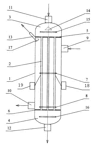
[0010] Such as figure 1 as shown in figure 1 As shown, a shell-and-tube heat exchanger consists of a shell (1), a heat exchange tube (2), an upper head (3), a lower head (4), an upper tube sheet (5), and a lower tube sheet ( 6), shell-side middle fluidization air distributor (7), shell-side lower fluidization air distributor (8), cold standby agent inlet (9), hot standby agent outlet (10), hot regeneration agent inlet ( 11), cooling regeneration agent outlet (12), hot stripping oil gas outlet (13), catalyst distribution plate (14) in the upper part of the tube pass, fluidization air distributor in the upper part of the tube pass (15), fluidization air distributor in the lower part of the tube pass (16), composed of arc-shaped baffles (17); the shell side is composed of the space between the shell (1), heat exchange tubes (2), upper tube sheet (5), and lower tube sheet (6), and the upper seal The head (3), the lower head (4) and the internal flow space of the heat exchange tu...


PUM


Abstract

The invention provides a shell and tube heat exchanger. The shell and tube heat exchanger mainly comprises a casing, heat exchange tubes, an upper head, a lower head, an upper tube plate, a lower tube plate, a middle-shell-side fluidization air distributor, a lower-shell-side fluidization air distributor, a cold spent catalyst inlet, a hot spent catalyst outlet, a hot regenerant inlet, a cold regenerant outlet and a hot stripped oil gas outlet. Heat transferring media flow in corresponding heat exchange tubes which are externally connected with temperature sensor contacts. According to the shell and tube heat exchanger, particle fluidizers are arranged in the heat exchanger to fluidize cold and hot particles, so that fluidized particles with fluid flow characteristics are obtained and flow in the heat exchanger in the flow direction, heat exchange between cold and hot solid particles is achieved, and the temperatures of the heat transferring media are monitored at any moment.

Description

technical field [0001] The invention relates to a shell-and-tube heat exchanger, which belongs to the technical field of machinery. Background technique [0002] When operating with a large solvent-to-oil ratio, in order to maintain a proper reaction temperature in the riser reactor, the regenerant must be cooled to maintain the heat balance in the reactor. The current method is to use an external heat extractor to exchange heat between the regenerant and water (steam), and cool the high-temperature regenerant to control the temperature of the process reaction process and maintain the reactor under the operating condition of a large agent-to-oil ratio. The internal temperature and heat balance, the heat taken out is used to generate superheated steam, which is incorporated into the steam pipe network. [0003] Although this method can increase the ratio of agent to oil to a certain extent, the problem with this method is that under the conditions that the carbon content of ...

Claims


Application Information

Patent Timeline
IPC IPC(8): F28D7/16C10G9/18C10G9/32
Inventor 钮建平
Owner WUXI ACC HEAT EXCHANGER
Why Eureka
Try Eureka