A Measuring Method of Pressure Transition Time in Fluid Seepage Environment

A technology of conduction time and seepage, applied in the measurement of fluid pressure, DC flow characteristics measurement, measurement devices, etc., can solve the problem of lack of scientific and effective experimental methods, etc., and achieve a high degree of intelligence.

Active Publication Date: 2016-02-10
CHINA NAT OFFSHORE OIL CORP +1
View PDF4 Cites 0 Cited by
  • Summary
  • Abstract
  • Description
  • Claims
  • Application Information

AI Technical Summary

Problems solved by technology

Therefore, it is necessary to measure the critical value of the fluid conduction time t in the seepage environment, but the research on this issue has always lacked scientific and effective experimental methods

Method used


Image

  • A Measuring Method of Pressure Transition Time in Fluid Seepage Environment
  • A Measuring Method of Pressure Transition Time in Fluid Seepage Environment
  • A Measuring Method of Pressure Transition Time in Fluid Seepage Environment

Examples


Embodiment 1

[0024] Embodiment 1. Measuring device for pressure transit time in fluid seepage environment

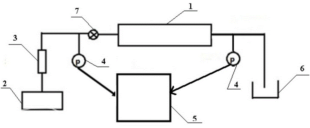
[0025] Such as figure 1 As shown, the measuring device for the pressure conduction time in the fluid seepage environment provided by the present invention includes a sand filling pipe 1, an advection pump 2, a liquid inlet container 3, a pressure sensor 4, a data acquisition and processing system 5 and a receiving container 6; The outlet of the liquid container 3 is connected with the inlet end of the sand filling pipe 1 , and the liquid inlet container 3 displaces the experimental fluid into the sand filling pipe 1 through the advection pump 2 . The outlet end of the sand filling pipe 1 communicates with the receiving container 6 for receiving the experimental fluid flowing out from the sand filling pipe 1 . A horizontal valve 7 is provided at the inlet end of the sand filling pipe 1 for disconnecting the communication between the sand filling pipe 1 and the liquid inlet container ...

Embodiment 2

[0028] Embodiment 2, measurement of pressure transmission time in fluid seepage environment

[0029] The pressure transit time in the fluid seepage environment is measured using the measuring device for the pressure transit time in the fluid seepage environment. Specific steps are as follows:

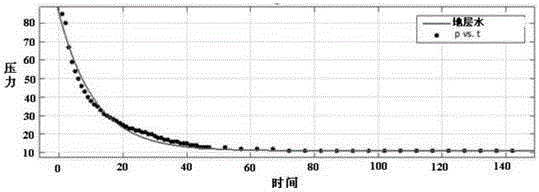
[0030] A reservoir with a permeability of 41.7mD was simulated by using sand-packing pipe 1, and the Bohai Sea SZ36-1 formation water was used as the experimental fluid.

[0031] (1) Use the prepared Bohai SZ36-1 formation water to saturate the sand filling pipe 1, and the formation water formula is shown in Table 1;

[0032] Table 1 Simulated formation water formula (amount of medicine required for 1L solution)

[0033]

[0034] (2) Use the advection pump 2 to continue to displace the Bohai Sea SZ36-1 formation water into the sand filling pipe 1, so that the pressure at the liquid inlet end rises to 0.085MPa;

[0035] (3) Stop the advection pump and close the horizontal valve 7 a...


PUM


Abstract

The invention discloses a measuring apparatus and method of pressure transmission time in a fluid percolation environment. The measuring apparatus comprises a percolation environment simulation device, a pressure control device, pressure sensors and a data acquisition and processing system; the pressure control device is communicated with the inlet end of the percolation environment simulation device and is used for providing pressure for fluid flow; the outlet end of the percolation environment simulation device is communicated with a receiving container; the pressure sensors are respectively arranged at the inlet end and the outlet end of the percolation environment simulation device; the pressure sensors are also connected with the data acquisition and processing system, and the data acquisition and processing system obtains the variation relation between the pressure difference and the time at the inlet end and the outlet end of the percolation environment simulation device according to pressure signals transmitted through the pressure sensors. The measuring method of the pressure transmission time in the fluid percolation environment has the advantages of accuracy, quickness and high automation and intelligence and the like. The measuring apparatus and method of the pressure transmission time in the fluid percolation environment fill in the gap of the technology of measuring pressure transmission end time in the fluid percolation environment and a scientific and effective real-time measuring apparatus and method indoors.

Description

technical field [0001] The invention relates to a measuring device and method for pressure transmission time in a fluid seepage environment, and belongs to the field of fluid pressure transmission laws in a porous medium seepage medium. Background technique [0002] Under the action of pressure, the fluid undergoes seepage movement in the rock, and when the pressure rises to a certain value P 1 After that, remove the pressure P 1 , the pressure begins to pass, and the fluid goes from a flowing state to a static state at last. After a certain interval of time t, pressurize again at the same end, when the fluid starts to move again, record the pressure P at this time 2 . If the fluid pressure in the sand filling pipe is completely transmitted, then P 2 It is the critical pressure that drives the fluid flow in the sand packing pipe. If the fluid pressure in the sand filling pipe is not completely transmitted, then P 2 If the superimposed effect is formed with the previous...

Claims


Application Information

Patent Timeline
Patent Type & Authority Patents(China)
IPC IPC(8): G01L11/00G01N11/08
Inventor 康晓东郑力会张健蒋珊珊曾杨赵文森
Owner CHINA NAT OFFSHORE OIL CORP
Why Eureka
Try Eureka