
Automatic collection device for production of steel balls

An automatic collection and steel shot technology, applied in the field of steel shot production and processing, can solve the problems of small size of steel shot, lower production efficiency, lower steel shot yield, etc., to achieve the effect of reducing production cost and improving efficiency

Inactive Publication Date: 2018-01-30
董小琳
View PDF0 Cites 1 Cited by
  • Summary
  • Abstract
  • Description
  • Claims
  • Application Information

AI Technical Summary

Problems solved by technology

[0003] However, in actual production, it is found that after the molten steel is thrown out by the centrifuge and before it falls into the cooling water pool, the semi-finished steel shot formed will react with the oxygen in the air due to its high temperature, and it is easy to appear hollow, abnormal shape, etc. Abnormal conditions, thus greatly reducing the yield of steel shot
At the same time, in the reaction of molten steel with oxygen in the air, its surface will be oxidized by oxygen in the air and rust will appear, resulting in poor surface color of the just finished product, which affects the quality of the product to a certain extent. The pellets are polished, which increases the production process and increases the production cost
[0004] After the production of steel shot is completed, since the steel shot is deposited at the bottom of the pool, it is difficult to collect the steel shot, and the process is more complicated
Due to the small size of the steel shot and its high mobility, the collection process will be cumbersome. In the process of collecting the steel shot, the production process of the steel shot must be stopped. The centrifuge cannot continuously throw out the molten steel, and the production continuity is low, resulting in production costs. increase, lower production efficiency

Method used


Image

  • Automatic collection device for production of steel balls

Examples


Embodiment Construction

[0018] The present invention is further described below in conjunction with accompanying drawing:

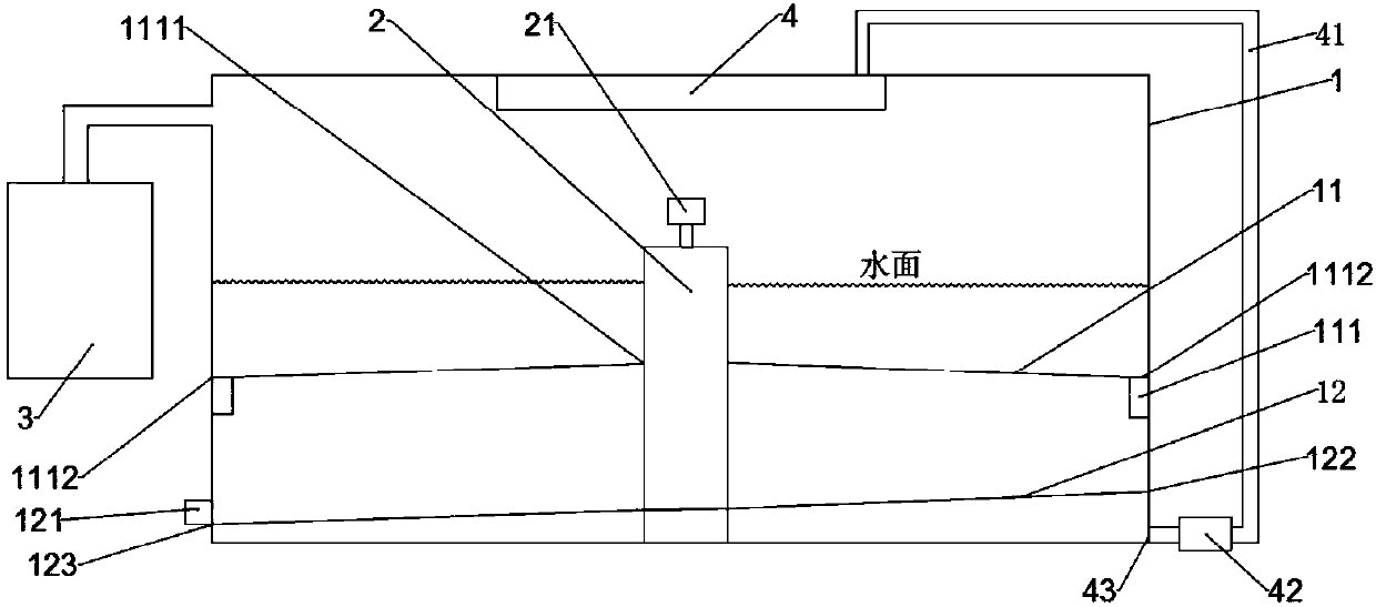
[0019] Such as figure 1 , the present invention is composed of a cooling pool 1 connected to a nitrogen source 3, and the nitrogen source 3 provides nitrogen for the entire production process to ensure the production quality of the steel shot. The inner center of the cooling pool 1 top surface is also provided with a water curtain cooling device 4, which is circular and sprays cold water downwards. Cooling pool 1 is equipped with cold water inside, and the liquid level of cold water is lower than rotor 2. A centrifuge 2 is arranged in the center of the inner bottom surface of the cooling pool 1 . The centrifuge 2 is provided with a temperature insulation layer.

[0020] In the cooling pool 1, a water-repellent layer 11 and a screen 12 are sequentially arranged from top to bottom, and the height of both is lower than that of the nozzle 21; Also be provided with valve 111, wat...


PUM


Abstract

The invention discloses an automatic collection device for production of steel balls and belongs to the field of production and processing of the steel balls. The device comprises a cooling pond, a centrifugal machine, a nitrogen source and a water curtain cooling device; the centrifugal machine is arranged in the middle of the bottom surface of the cooling pond, and the water curtain cooling device is arranged in the middle of the top surface of the centrifugal machine; a water insulation layer is arranged in the middle of the cooling pond, a valve is arranged on the water insulation layer, and the height of the water insulation layer is smaller than that of a rotation mouth of the centrifugal machine; screen cloth is arranged on the lower portion of the cooling pond, the pore diameters of the screen cloth are smaller than the external diameters of the steel balls to be produced, and ball collection openings are formed in the side wall of the cooling pond of which the height is equalto the screen cloth; a water outlet is formed in the side wall of the cooling pond, below the screen cloth. The automatic collection device for production of the steel balls has the advantages that the steel balls are automatically collected, continuous production can be achieved in the collection process, the production efficiency is improved, and the production cost is lowered. Water circulationand utilization can be automatically achieved, and the device saves energy and is environmentally friendly.

Description

technical field [0001] The invention belongs to the field of steel shot production and processing, and in particular relates to an automatic collection device for steel shot production. Background technique [0002] In the steel shot production process of the prior art, the centrifugal method is generally used to realize the forming of the steel shot, and the steel shot produced by the centrifugal method has the advantages of good roundness and less conjoined bodies. The principle of the centrifuge method is: put molten steel in a molten state into a centrifuge, and throw the molten steel out of the centrifuge by centrifugal force. The centrifuge is located in the middle of a cooling water pool, so the molten steel thrown out of the centrifuge falls into the cooling water pool. In cooling water, quickly cool down and form. [0003] However, in actual production, it is found that after the molten steel is thrown out by the centrifuge and before it falls into the cooling wate...

Claims


Application Information

Patent Timeline
Patent Type & Authority Applications(China)
IPC IPC(8): B22D13/10
Inventor 董小琳
Owner 董小琳
Learn More