
Control system and method for buildings and building groups

A control method and control system technology, applied in the field of construction, can solve the problems of lack of versatility, different structures, and high cost, and achieve the effect of improving versatility and realizing intelligence

Active Publication Date: 2014-05-21
TSINGHUA UNIV +1
View PDF6 Cites 9 Cited by
  • Summary
  • Abstract
  • Description
  • Claims
  • Application Information

AI Technical Summary

Problems solved by technology

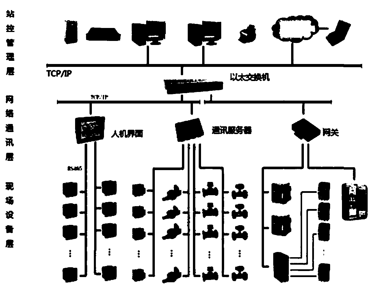
However, in such figure 1 In the control system shown in , the problem is that the architecture of the three-layer centralized control system including, for example, the station control management layer, the network communication layer, and the field device layer is different from the building space structure. In order to realize the building management function, Requires a lot of configuration and networking work
[0003] The consequence of this is that the configuration of the control system for the entire building must be carried out case-by-case, which is costly and lacks versatility

Method used


Image

  • Control system and method for buildings and building groups
  • Control system and method for buildings and building groups
  • Control system and method for buildings and building groups

Examples


no. 1 example

[0104] The application of the control method and system for buildings according to the present invention will be described in detail below. Generally, when a fire occurs in a building, if the fire warning can be carried out early, the safety of the building can be greatly improved.

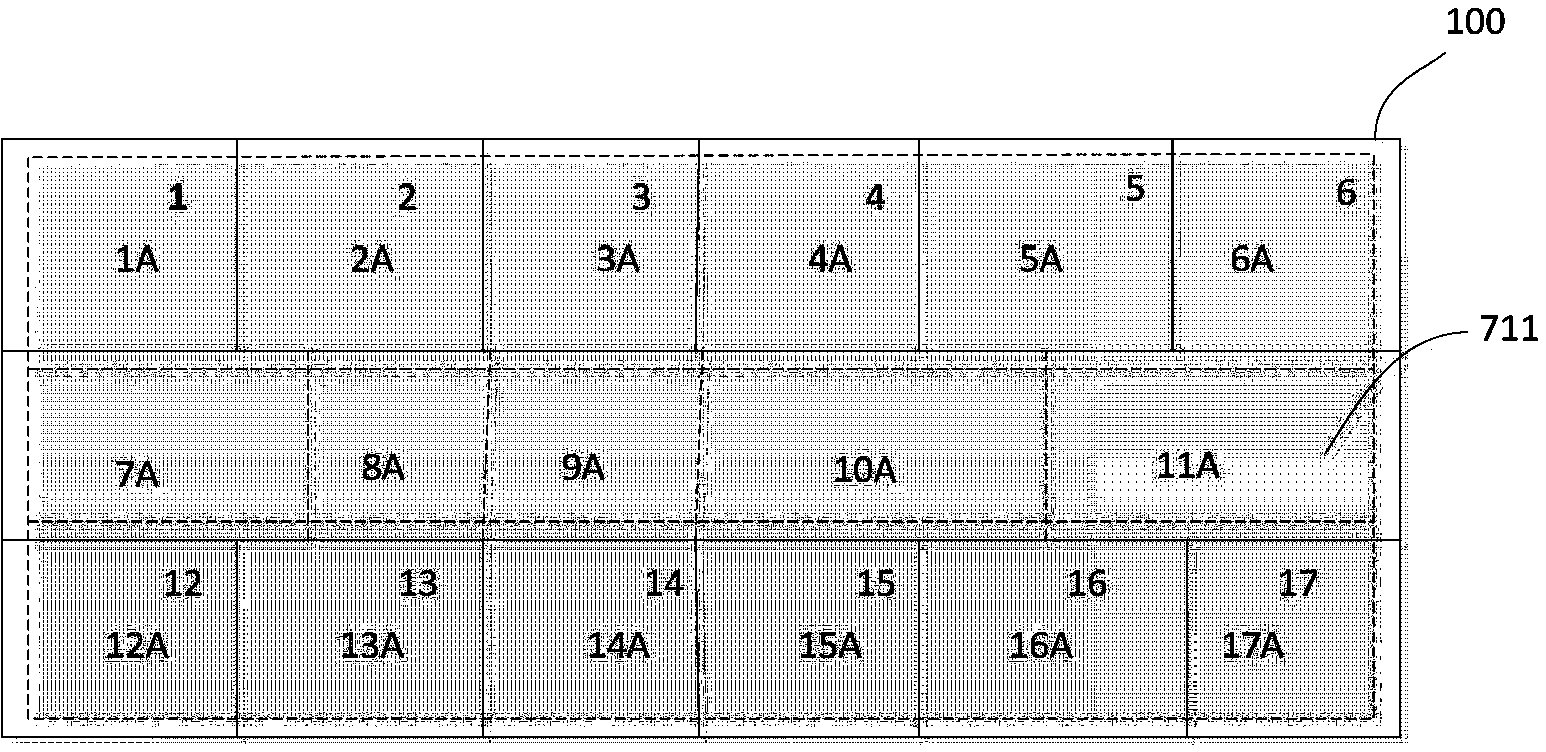
[0105] Figure 9 A system for controlling a building is shown, the system includes a node control network 400, the node control network 400 is composed of node units 1-69 arranged in a plurality of spatial regions divided into buildings, the building For the division of spatial regions, please refer to the above, and will not be described in detail here.

[0106] Each node unit 1-69 is respectively configured to monitor at least one of HVAC, lighting, daylighting, security, water supply, energy saving and daylighting of the corresponding space area. Such as Figure 9 As shown in , each node unit is equipped with a fire monitoring module (not shown), which is used to judge whether a fire has occ...

no. 2 example

[0110] The following will continue to refer to the example of distributed computing in a building by the node control network 500 shown in FIG. 100 . It should be noted that in building control, distributed computing is usually required. For example, in the water pipe network system of a building, it is usually necessary to understand the water flow distribution in the water pipe network, and control and adjust based on the water flow distribution field. However, in reality, it is impossible to measure all the water pipe networks, and it can only be detected at specific points, so that distributed calculations can be performed based on the existing Gauss-Seidel iterative algorithm to obtain the water pipe network model of the entire building . Common physical equations may be nonlinear calculation equations, but in the present invention, distributed calculations are used to approximate linear calculation equations between adjacent node units, so as to obtain required calculati...


PUM


Abstract

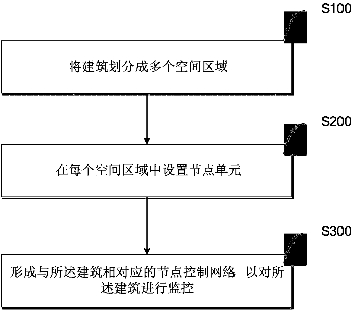
The invention provides a control method for buildings. The control method for the buildings comprises the following steps of dividing the buildings into a plurality of space regions which are mutually adjacent and independent; setting a node unit in every space region and enabling the node units to be used for controlling the space regions; performing network interconnection on the node units in the space regions which are adjacent in space, designing the adjacent node units to be in mutual communication to form into a node control network which is corresponding to the buildings and monitoring the buildings through the node control network. Compared with the existing three-layer control method, the new building control method has the advantages of being good in universality and low in construction cost. The invention also discloses a control system for the buildings and building groups.

Description

technical field [0001] The invention relates to the technical field of buildings, in particular to a novel control system and method for buildings or building groups. Background technique [0002] In the existing building control system, the central control of the building is usually realized around the existing equipment or the equipment provider. At present, the most commonly used control method is the hierarchical centralized control method. Such as figure 1 As shown in , centralized control of, for example, a building's air conditioning system, fire system, and security system is carried out in a central control room. However, in such figure 1 In the control system shown in , the problem is that the architecture of the three-layer centralized control system including, for example, the station control management layer, the network communication layer, and the field device layer is different from the building space structure. In order to realize the building management f...

Claims


Application Information

Patent Timeline
Patent Type & Authority Applications(China)
IPC IPC(8): G05B19/418
Inventor 江亿姜子炎赵千川陈曦张辉杨锐柳哲代允闯吴楠乔利锋宋芳婷
Owner TSINGHUA UNIV
Learn More