Interference object detection method and equipment

A technique for interfering with targets and setting conditions, which is applied in character and pattern recognition, image data processing, instruments, etc., and can solve problems such as high probability of false detection

Active Publication Date: 2014-05-21
ZHEJIANG DAHUA TECH CO LTD
View PDF4 Cites 1 Cited by
  • Summary
  • Abstract
  • Description
  • Claims
  • Application Information

AI Technical Summary

Problems solved by technology

[0010] Embodiments of the present invention provide a method and device for detecting interference targets, which are used to solve the problem of high probability of false detection in the detection of moving targets in the prior art

Method used


Image

  • Interference object detection method and equipment
  • Interference object detection method and equipment
  • Interference object detection method and equipment

Examples


Embodiment 1

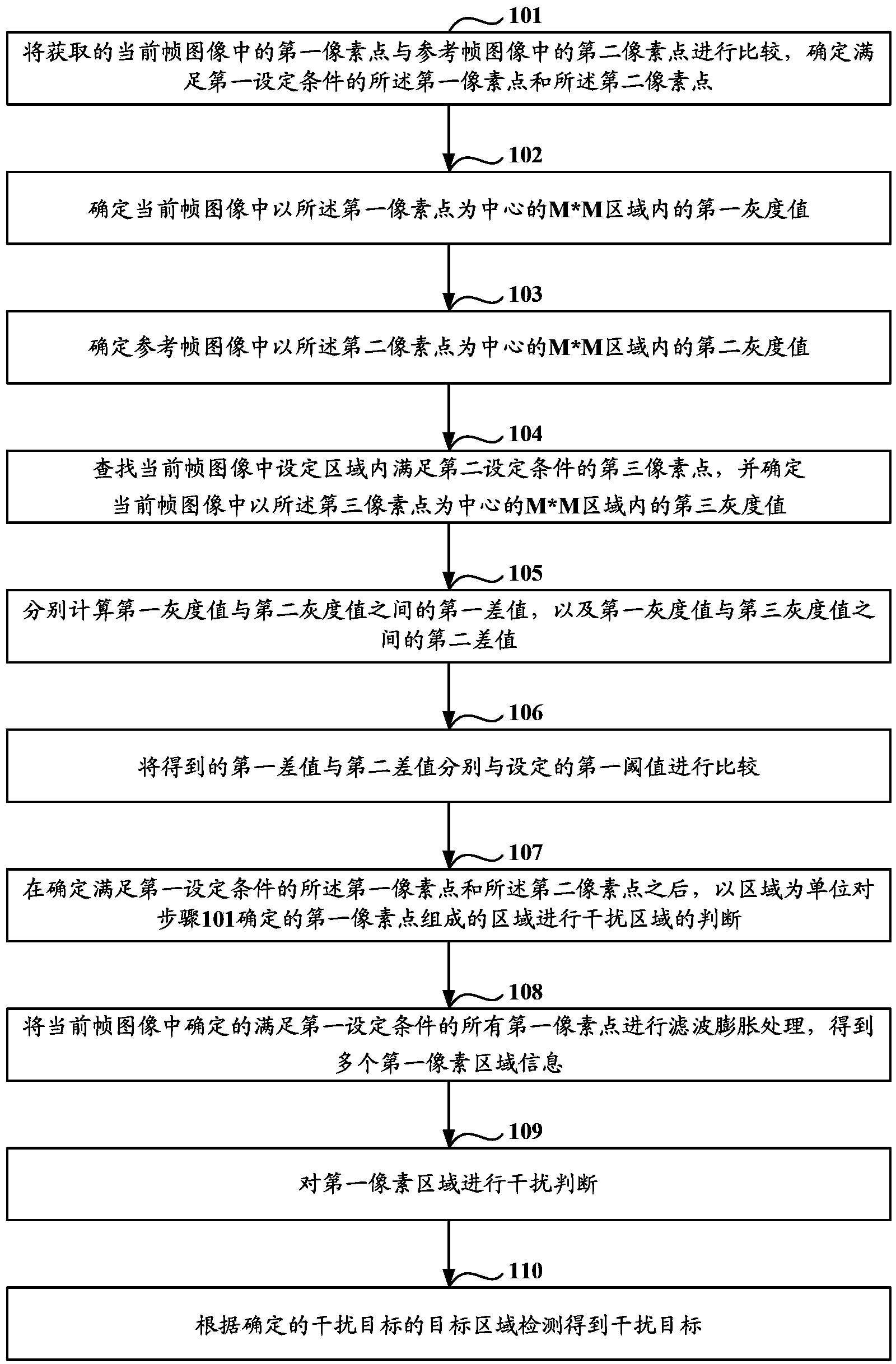
[0034] Such as figure 1 As shown, it is a flow chart of a method for detecting an interference target in Embodiment 1 of the present invention, and the method includes:

[0035] Step 101: Compare the acquired first pixel point in the current frame image with the second pixel point in the reference frame image, and determine the first pixel point and the second pixel point satisfying the first set condition.

[0036] In step 101, when obtaining the image information of the current frame, it is determined that the image information of the reference frame corresponding to the image information of the current frame is selected, and the image of the previous Nth frame in the image information is selected as the image information of the reference frame.

[0037] Specifically, in a set of image information, two frame images set at a frame number interval N are the current frame image and the reference frame image, wherein N can be changed and determined according to needs. For examp...

Embodiment 2

[0120] Such as Image 6 As shown, it is a schematic structural diagram of an interference target detection device according to Embodiment 2 of the present invention. The device includes: a determination module 11, a gray value calculation module 12, and an interference target detection module 13, wherein:

[0121] A determining module 11, configured to compare the acquired first pixel point in the current frame image with the second pixel point in the reference frame image, and determine the first pixel point and the second pixel point satisfying the first setting condition. pixel.

[0122] Grayscale value calculation module 12, used to determine the first grayscale value in the M*M area centered on the first pixel point in the current frame image, where M is an integer not less than 3, and find the current frame The third pixel point in the set area in the image that satisfies the second set condition, and obtain the third gray value in the M*M area centered on the third pix...


PUM


Abstract

The invention discloses an interference object detection method and equipment. The method comprises steps that: first pixel points of a present frame image are contrasted with second pixel points of a reference frame image to determine the first pixel points and the second pixel points which satisfy conditions, and a first tonal value is acquired according to the first pixel points; third pixel points are searched from the present frame image, and a third tonal value is acquired; a second tonal value in the reference frame image is acquired through the second pixel points, a first difference value of the first tonal value and the second tonal value is respectively calculated, a second difference value of the first tonal value and the third tonal value is respectively calculated, if the first difference value and the second difference value are both smaller than a first set threshold, the first pixel points is determined to be pixel points of an interference object, and the interference object is detected according to the determined pixel points of the interference object. Compared with the prior art, a calculation method is relatively simple through a point mode, and accuracy for determining the interference object is relatively high.

Description

technical field [0001] The invention relates to the field of intelligent video monitoring, in particular to a method and equipment for detecting an interference target. Background technique [0002] Moving target detection is the basic technical link of intelligent video surveillance technology, and it is very important for subsequent target classification, tracking and behavior analysis and processing. The detection of the moving object is to remove the background and extract the moving area of ​​interest from the image sequence, not only to detect the moving area from the background image, but more importantly, to extract the effective moving object. [0003] However, when detecting the moving area in the monitoring scene, it is often encountered that there are moving interference targets in the background of the moving area, such as shaking branches, rain and snow, water waves, etc., which will make the detected When there is an error in a valid moving target, for exampl...

Claims


Application Information

Patent Timeline
Patent Type & Authority Applications(China)
IPC IPC(8): G06K9/00G06T7/00
Inventor 潘华东潘石柱孙莉田建国吴良健周洪涛张兴明傅利泉朱江明吴军吴坚
Owner ZHEJIANG DAHUA TECH CO LTD
Why Eureka
Try Eureka