Magnetic field centralization configuration antenna

A magnetic field and configuration technology, applied in antennas, loop antennas, electromagnetic wave systems, etc., can solve problems such as electromagnetic interference, reduce radio wave intensity, and reduce wireless charging efficiency

Active Publication Date: 2014-05-21
AUTOMOTIVE RES & TESTING CENT
View PDF5 Cites 10 Cited by
  • Summary
  • Abstract
  • Description
  • Claims
  • Application Information

AI Technical Summary

Problems solved by technology

[0009] As mentioned above, the coil group of the existing wireless charging device is prone to magnetic flux leakage and reduces the efficiency of wireless charging. There will be a strong magnetic field distribution in the non-electromagnetic field transmission area, causing electromagnetic interference problems. Although the gate antenna can be concentrated Radio signal, but it will consume part of the radio signal of the power supply coil and reduce the radio wave intensity. Therefore, the main purpose of the present invention is to provide a configuration antenna with a concentrated magnetic field, which mainly uses resonance to concentrate the magnetic field radiated from the antenna to solve the current The coil group using electromagnetic induction produces magnetic flux leakage, the area where the non-electromagnetic field is transmitted will have the problem of strong magnetic field distribution and electromagnetic interference, and solve the problem of the reduction of the radio wave intensity of the gate antenna

Method used


Image

  • Magnetic field centralization configuration antenna
  • Magnetic field centralization configuration antenna
  • Magnetic field centralization configuration antenna

Examples


Embodiment Construction

[0047] In order to make the object, technical solution and advantages of the present invention clearer, the embodiments of the present invention will be further described in detail below in conjunction with the accompanying drawings. Here, the exemplary embodiments and descriptions of the present invention are used to explain the present invention, but not to limit the present invention.

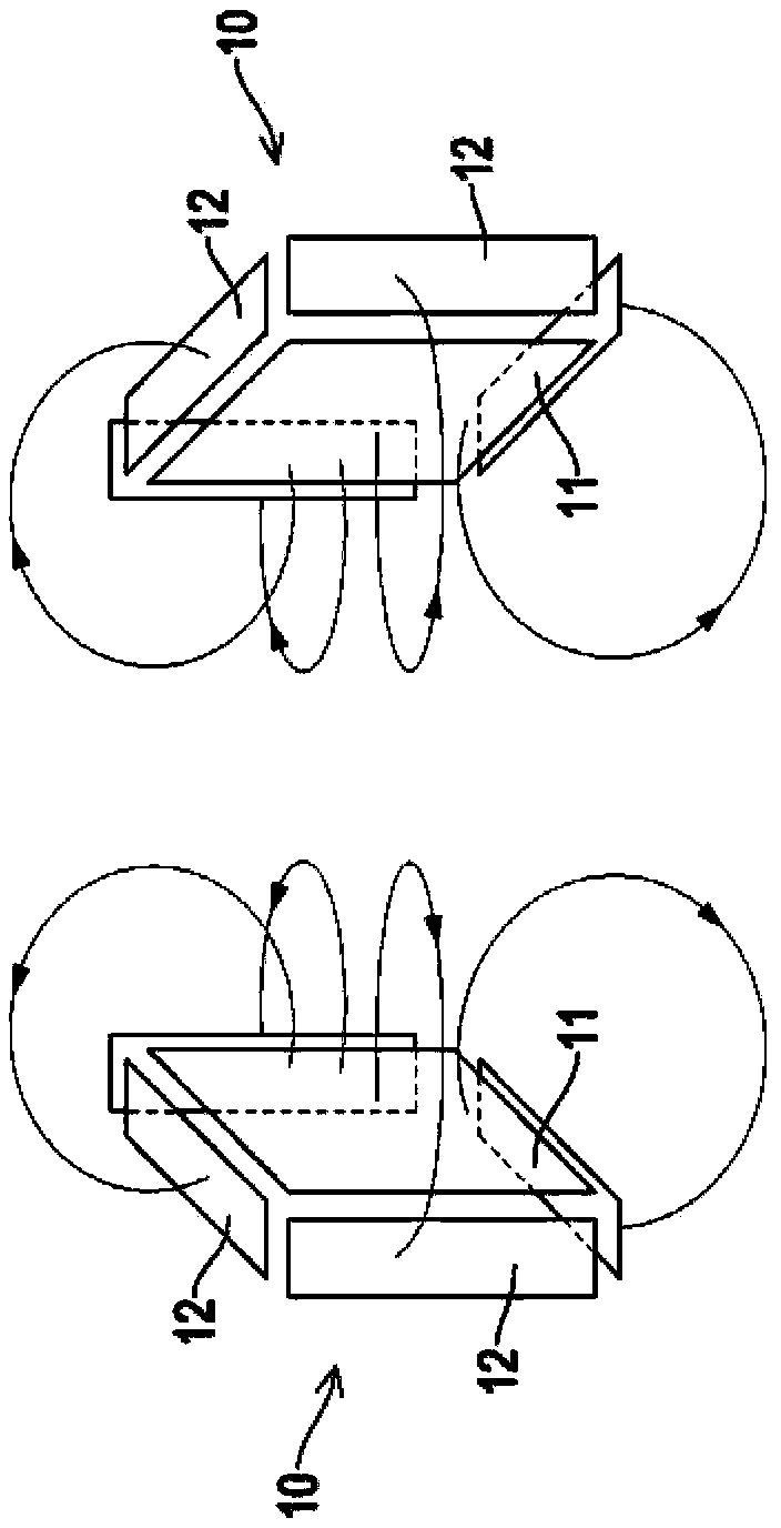
[0048] For a preferred embodiment of the present invention, please refer to figure 1As shown, a concentrated magnetic field antenna 10 includes a main coil 11 and two pairs of auxiliary coils 12, 12', wherein each pair of auxiliary coils 12, 12' is respectively arranged in a pairwise manner, and the main coil 11 and each pair of auxiliary coils 12, 12' are respectively flat. In this embodiment, the outlines of the main coil 11 and the auxiliary coils 12, 12' are roughly rectangular, wherein the main coil 11 has four sides, and each pair of auxiliary coils The coils 12 , 12 ′ are arranged a...


PUM


Abstract

An embodiment of the invention provides a magnetic field centralization configuration antenna. The antenna comprises a main coil and more than one pair of auxiliary coils. The main coil and each of the more than one pair of auxiliary coils all comprise more than one wire sections, a virtual datum plane is defined on each wire section, the more than one pair of auxiliary coils is arranged on the periphery of the main coil, and included angels are formed between the virtual datum planes and the virtual datum plane of the main coil. Magnetic force lines generated by the main coil are radiated outwards from the virtual datum plane, and magnetic force lines generated by all wire sections of the more than one pair of auxiliary coils guide the magnetic force lines on the periphery of the main coils to the virtual datum planes to centralize and enhance the magnetic force lines of the main coil, and accordingly, flux leakage is reduced, and the problems of flux leakage and electromagnetic interference occurring easily outside transmission action areas of coil assemblies using electromagnetic induction are solved.

Description

technical field [0001] The invention relates to an antenna, in particular to an antenna capable of concentrating the radiation direction of magnetic force lines of a magnetic field. Background technique [0002] Due to the rapid development of science and technology, from small portable electronic products to large electric cars / locomotives, they use built-in rechargeable batteries to reduce environmental pollution and allow users to use them at any time. However, when you want to charge the battery, the common problem is that you need to connect the charging cable to charge the battery. However, different products use different charging cable connector specifications due to different manufacturers, and there is a problem of inconvenient use. . [0003] Therefore, the existing technology is to charge the battery by means of wireless charging, please refer to Figure 8 As shown, it is provided with a wireless receiver 71 on an electronic product or an electric car / locomotive...

Claims


Application Information

Patent Timeline
Patent Type & Authority Applications(China)
IPC IPC(8): H01Q7/00H01Q1/36H02J17/00H02J50/20H02J50/70
Inventor 江朝文
Owner AUTOMOTIVE RES & TESTING CENT
Why Eureka
Try Eureka