Tuning device of optical signal transmitting device for communication

A technology of a tuning device and a transmitting device is applied in the field of tuning devices to achieve the effects of convenient tuning control, good stability and simple external modification

Inactive Publication Date: 2014-05-21
WUXI CINSEC INFORMATION TECH
View PDF0 Cites 4 Cited by
  • Summary
  • Abstract
  • Description
  • Claims
  • Application Information

AI Technical Summary

Problems solved by technology

At present, the tuning interval is 0.8nm, but the tuning speed generally requires a few seconds of tuning time

Method used


Image

  • Tuning device of optical signal transmitting device for communication
  • Tuning device of optical signal transmitting device for communication
  • Tuning device of optical signal transmitting device for communication

Examples


Embodiment Construction

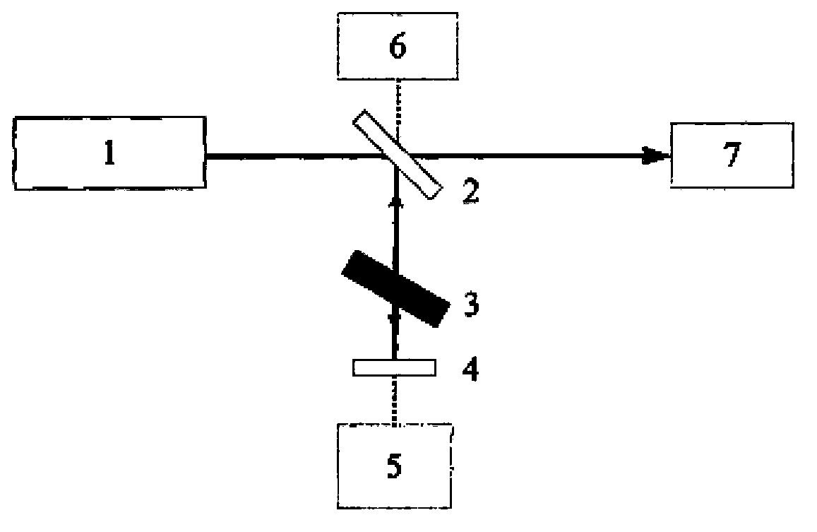
[0029] Such as figure 1 As shown, the device of the present invention is composed of a laser 1, a beam splitter 2, a variable attenuation sheet 3, a reflector 4, a spectrometer 5, a detector 6, and an optical power meter 7. The detector 6 generally adopts a photodiode or a photomultiplier tube detector.

[0030] The specific implementation of the method of the present invention is as follows: figure 1 As shown, the laser 1 adopts a continuous semiconductor laser with an output wavelength of 1060nm. Because it is in the invisible band, one visible light can be introduced during the experiment as an auxiliary optical path to facilitate subsequent optical path adjustment; ensuring that the feedback light intensity can meet the requirements of the laboratory If necessary, try to increase the transmission ratio of the beam splitter to make the output light power as large as possible. Through the analysis of experimental data, the transmission ratio of the beam splitter is selected to...


PUM


Abstract

The invention provides a tuning device of an optical signal transmitting device. The turning device comprises a laser (1), a spectroscope (2), a variable attenuator (3) and a reflection mirror (4). The outer cavity of the laser is formed by the reflection mirror (4). The turning device is characterized in that the outer cavity is also provided with an optical device (8) with an adjustable optical length, and through adjusting the variable attenuator (3) and the optical device (8) with the adjustable optical length at the same time, the turning output of the optical signal is realized by using a self mixing effect.

Description

Technical field [0001] The invention relates to a tuning device for an optical signal transmitting device for communication, in particular to a device for tuning the output wavelength of a semiconductor laser. technical background [0002] Use light to transmit language, data, images or other information. Currently, it mainly refers to laser communication. The conditions for sending signals with light (including visible light, invisible light, laser, infrared, and ultraviolet) are: modulated light source, photosensitive detector and receiver, and the medium through which light can pass. Optical communication systems can be divided into two categories: one is called "wireless" optical communication, and its optical signals radiate to a distance through space or the atmosphere; the other is called "guided wave" optical communication, also called "wired" Optical Communication. That is, the electromagnetic waves that constitute light propagate along a constrained path or optical t...

Claims


Application Information

Patent Timeline
Patent Type & Authority Applications(China)
IPC IPC(8): H04B10/50
Inventor 耿振民
Owner WUXI CINSEC INFORMATION TECH
Why Eureka
Try Eureka