Turning-milling combination machine

A compound machine, turning and milling technology, which is applied in the direction of metal processing machinery parts, large fixed members, clamping, etc., can solve the problems of unsatisfactory processing efficiency and stability

Inactive Publication Date: 2014-05-28
东莞市美迈士机械科技有限公司
View PDF6 Cites 8 Cited by
  • Summary
  • Abstract
  • Description
  • Claims
  • Application Information

AI Technical Summary

Problems solved by technology

However, the existing turning-milling machines are not ideal in terms of processing efficiency and stability, and are not satisfied with the requirements of actual production.

Method used


Image

  • Turning-milling combination machine
  • Turning-milling combination machine
  • Turning-milling combination machine

Examples


Embodiment Construction

[0022] The present invention will be described in further detail below in conjunction with the accompanying drawings.

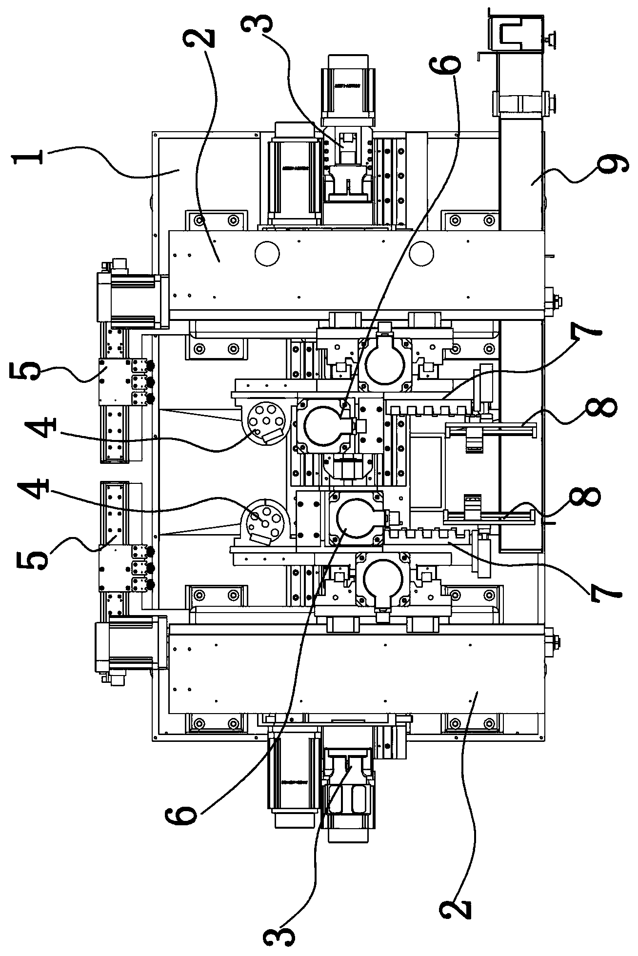
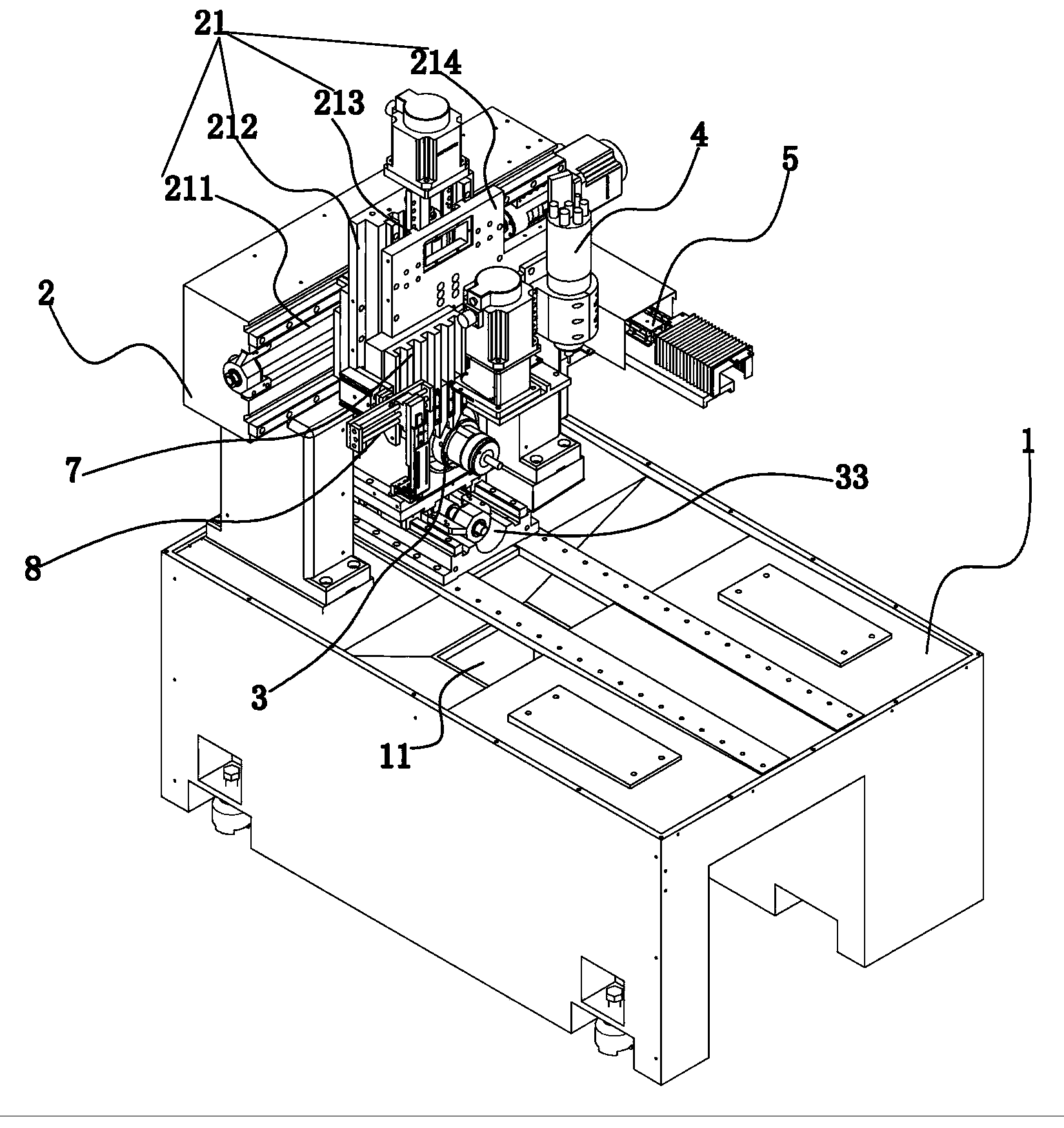
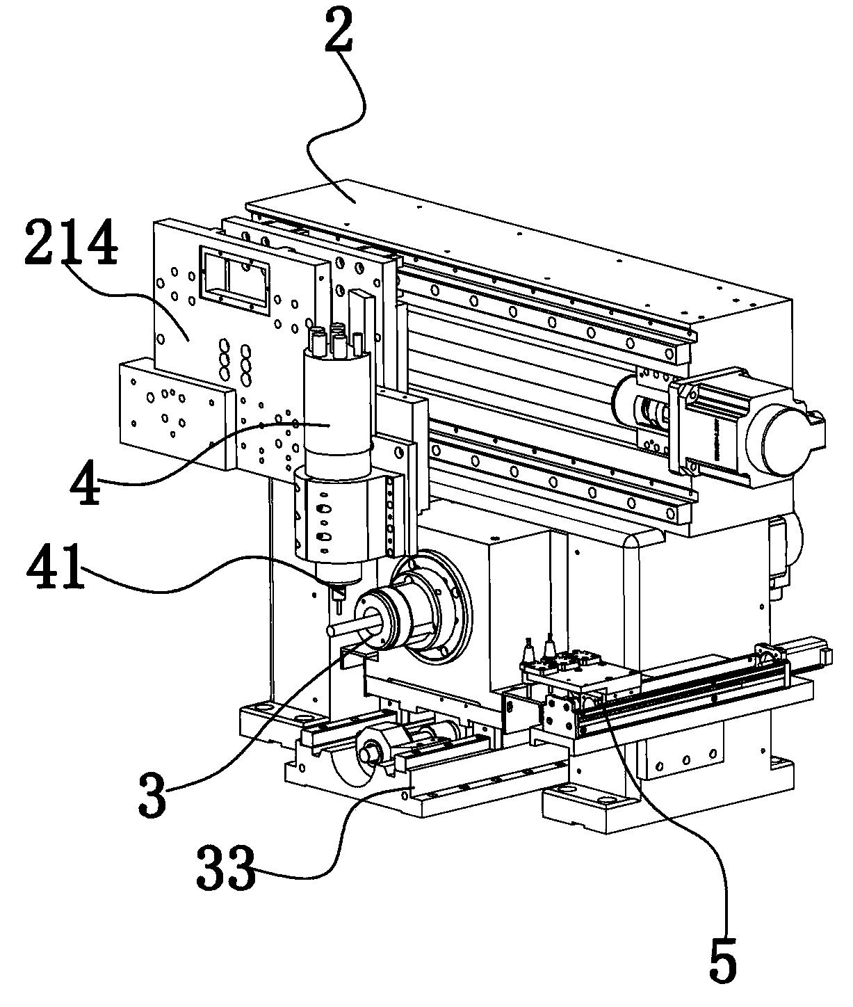
[0023] Figure 1 to Figure 8 A mill-turn machine according to an embodiment of the present invention is schematically shown.

[0024] The turning and milling compound machine includes machine base 1, gantry frame 2, horizontal spindle base 3, vertical spindle arm 4, vertical spindle arm tool changing mechanism 5, power turret 6, tool rack 7, and material receiving manipulator 8 and receiving channel 9.

[0025] Machine base 1: used to install gantry frame 2, vertical spindle arm 4, vertical spindle arm tool change mechanism 5, horizontal spindle seat 3, power turret 6, row tool holder 7, receiving manipulator 8 and receiving channel 9. The machine base 1 is provided with a drain hole 11, and the drain hole 11 is set in the middle of the upper end of the machine base 1 to drain away the water used when the turning-milling compound machine is working.

[002...


PUM


Abstract

The invention discloses a turning-milling combination machine and belongs to the field of turning-milling machining. The turning-milling combination machine comprises a portal frame, a horizontal main shaft base, a vertical main shaft arm, a power tool tower and a row tool rest. The horizontal main shaft base is arranged in a gantry of the portal frame in a penetrating mode. A transmission mechanism is arranged on the portal frame. The vertical main shaft arm, the power tool tower and the row tool rest are arranged on the transmission mechanism, so that vertical plane moving of the vertical main shaft arm, the power tool tower and the row tool rest is achieved, and a workpiece is machined. The turning-milling combination machine is high in machining efficiency and stable in performance.

Description

technical field [0001] The invention relates to the field of turning and milling processing, in particular to a turning and milling compound machine. Background technique [0002] Since the beginning of the 21st century, the development of mechanical processing technology and equipment worldwide has been changing with each passing day and advancing by leaps and bounds. As the most common and basic production equipment for mechanical processing, the development direction of CNC lathes further presents trends such as high precision, intelligence, and compounding. [0003] CNC compound machining is to put several different processing techniques on the same CNC machine tool to realize the processing of parts. For example, turning, milling, drilling, etc. can be performed on a CNC machine tool. One of the most popular advanced manufacturing technologies in the field. The biggest advantage of the CNC machine tool with compound processing capability is that it can realize the proc...

Claims


Application Information

Patent Timeline
Patent Type & Authority Applications(China)
IPC IPC(8): B23P23/02
CPCB23P23/02B23B29/244B23Q1/012B23Q1/70B23Q3/15766B23Q7/048B23Q2707/04
Inventor 彭庆营
Owner 东莞市美迈士机械科技有限公司
Why Eureka
Try Eureka