Automatic hydraulic braking pressure supply device for unmanned aerial vehicle

A technology for hydraulic braking and unmanned aerial vehicles, which is applied to braking transmissions, aircraft braking arrangements, brakes, etc., can solve the problems of limited installation location, high cost, and high system failure rate, and achieves simple connection and failure. The effect of low rate and low energy consumption

Inactive Publication Date: 2014-05-28
HARBIN
View PDF5 Cites 4 Cited by
  • Summary
  • Abstract
  • Description
  • Claims
  • Application Information

AI Technical Summary

Problems solved by technology

[0003] (1) The installation position is limited: the hydraulic pump shaft must be connected to the engine shaft, there is no choice for the position of the hydraulic pump, and the connection process between the hydraulic pump shaft and the engine shaft requires high requirements
[0004] (2) The hydraulic pump idles for a long time: when not braking, the hydraulic pump is also in an idle state, which affects the efficiency of the engine and the life of the hydraulic pump
[0005] (3) The electro-hydraulic servo valve has high requirements on oil precision, high failure rate of the system, and high cost

Method used


Image

  • Automatic hydraulic braking pressure supply device for unmanned aerial vehicle

Examples


Embodiment Construction

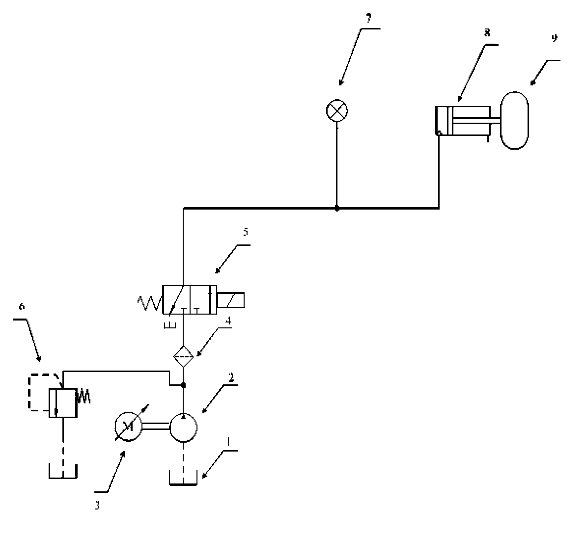
[0012] The present invention will be described in detail below in conjunction with the accompanying drawings. The UAV automatic hydraulic brake pressure supply device includes a hydraulic oil tank 1, a quantitative hydraulic pump 2, a frequency conversion motor 3, an oil filter 4, a brake valve 5, an overflow valve 6, a brake sensor 7, a brake actuator 8, and a quantitative hydraulic pump 2 The drive shaft of the fixed displacement hydraulic pump 2 is connected to the output shaft of the variable frequency motor 3, the oil suction port of the quantitative hydraulic pump 2 is connected to the oil tank 1, the oil outlet of the quantitative hydraulic pump 2 is connected to one end of the oil filter 4 and the overflow valve 6, and the other end of the oil filter 4 One end is connected to the inlet of the brake valve 5, and the outlet of the brake valve 5 is connected to one end of the brake pressure sensor 7 and the brake cylinder 8 respectively.

[0013] The pressure of the hydra...


PUM


Abstract

The invention belongs to an unmanned aerial vehicle hydraulic technology, and relates to an automatic hydraulic braking pressure supply device for an unmanned aerial vehicle. The device comprises a hydraulic oil tank (1), a hydraulic constant delivery pump (2), a variable frequency motor (3), an oil filter (4), a brake valve (5), an overflow valve (6), a brake sensor (7) and an brake actuating cylinder (8), wherein a driving shaft of the hydraulic constant delivery pump (2) is connected with an output shaft of the variable frequency motor (3); an oil suction port of the hydraulic constant delivery pump (2) is connected with the oil tank (1); an oil outlet of the hydraulic constant delivery pump (2) is simultaneously connected with one end of the oil filter (4) and the overflow valve (6); the other end of the overflow valve (6) is connected with the oil tank (1); the other end of the oil filter (4) is connected with an inlet of the brake valve (5); an outlet of the brake valve (5) is connected with the brake sensor (7) and one end of the brake actuating cylinder (8) respectively. According to the device, the brake valve is low in cost, and has low requirements on the accuracy of oil, so that the device is low in failure rate and cost.

Description

technical field [0001] The invention belongs to the hydraulic technology of drones, and relates to an automatic hydraulic brake pressure supply device for drones. Background technique [0002] In the existing UAV braking device, the electro-hydraulic control servo hydraulic system is generally used, and the brake is realized by controlling the flow and pressure of the system by controlling the opening of the electro-hydraulic servo valve. In some cases, the pump is idling, and the electro-hydraulic servo valve is unloaded in the neutral position, and the hydraulic pump works for a long time, which affects the life of the hydraulic pump. This approach has 3 disadvantages: [0003] (1) The installation position is limited: the hydraulic pump shaft must be connected to the engine shaft, there is no choice for the position of the hydraulic pump, and the connection process between the hydraulic pump shaft and the engine shaft requires high requirements. [0004] (2) The idling ...

Claims


Application Information

Patent Timeline
Patent Type & Authority Applications(China)
IPC IPC(8): B64C25/44B60T13/20
Inventor 谷峰
Owner HARBIN
Why Eureka
Try Eureka