
A Portal Crane Position Monitoring System Based on Optical Code and Electronic Compass

A portal crane, electronic compass technology, applied in cranes, transportation and packaging, load hanging components and other directions, can solve the problems of high equipment cost and construction cost, radio communication interference, low precision, etc., to reduce the driver's work intensity , The effect of lifting operation safety, production safety and efficiency improvement

Active Publication Date: 2016-09-14
ZHONGCHUAN NO 9 DESIGN & RES INST
View PDF6 Cites 0 Cited by
  • Summary
  • Abstract
  • Description
  • Claims
  • Application Information

AI Technical Summary

Problems solved by technology

The problem existing in the existing technology is: the GPS positioning accuracy of the civilian level is generally >10m. If the accuracy is to be improved to the m level, a ground base station needs to be established. The construction cost of the ground base station is obviously higher than that of the portal crane control system. cost, in addition to interference with radio communications
The measuring wheel and the photoelectric encoder are installed on the driving gear of the rotating mechanism, the equipment cost and construction cost are high, the mechanical tolerance and the cumulative error of the equipment operation need to be corrected frequently, the precision is low, the volume is large, and the digital signal output cannot be realized

Method used


Image

  • A Portal Crane Position Monitoring System Based on Optical Code and Electronic Compass

Examples


Embodiment Construction

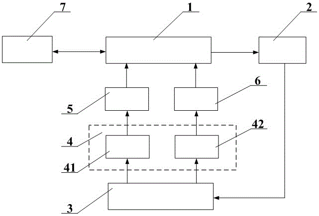
[0008] See attached figure 1 , the present invention is formed by connecting a PLC mainframe 1 with an electronic compass 5 arranged on a portal crane 4, a photoelectric encoder 6 and a frequency converter 2 arranged on a driving device 3, and the electronic compass 5 is arranged on a boom rotating On the luffing mechanism 41; the photoelectric encoder 6 is arranged on the crane traveling mechanism 42; the driving device 3 is driven by the frequency converter 2; the frequency converter 2, the electronic compass 5 and the photoelectric encoder 6 are connected with a touch screen Or the PLC host 1 connected to the industrial computer 7 is connected to form a crane control closed loop; the PLC host 1 is provided with a collision danger area of ​​the crane jib and an alarm or shutdown protection program, and the PLC host 1 sends an alarm when the crane jib enters the dangerous area Or send a stop protection signal to the frequency converter 2, and dynamically display it on the tou...


PUM


Abstract

The invention discloses a portal crane position monitoring system based on an optical coder and an electronic compass. The portal crane position monitoring system is characterized in that the electronic compass is arranged on a rotating / amplitude varying mechanism of the crane; the optical coder is arranged on a travelling mechanism; a drive device is provided with a frequency converter; the electronic compass, the optical coder and the frequency converter are connected with a PLC (Programmable Logic Controller) host machine to form a crane control closed loop; and when a crane boom enters a danger area, the PLC host machine is used for sending an alarm or sending a shutdown protection signal to the frequency converter, so that real-time monitoring on the crane boom and the travelling mechanism is realized. Compared with the prior art, the portal crane position monitoring system disclosed by the invention has warning and shutdown protection functions and is used for precisely monitoring the operating state of the crane boom and the travelling mechanism, so that the crane boom is prevented from having collision with surrounding objects during the working process, the operation security in a lifting process of the crane during cross-operation is guaranteed, the work intensity of a driver is reduced, and the production safety and efficiency are greatly improved.

Description

technical field [0001] The invention relates to the technical field of industrial automation control, in particular to a portal crane position monitoring system based on an optical encoder and an electronic compass. Background technique [0002] Portal cranes are used for loading and unloading workpieces in shipyards or ports. They are important production equipment in shipyards. They mainly include lifting, luffing, rotating and walking mechanisms. Rotating, the traveling mechanism drives the gantry crane to move along the ground track. When the portal crane is in operation, it is necessary to rely on the driver and ground dispatchers to observe the position of the crane with the naked eye, and realize early warning based on experience. However, manual observation has no quantitative data, and manual adjustment has no reference coordinates, so the operation is prone to deviation, resulting in frequent safety accidents of cranes. Now the equipment density of the factory is...

Claims


Application Information

Patent Timeline
Patent Type & Authority Patents(China)
IPC IPC(8): B66C23/88B66C13/46
Inventor 熊冠楚张军汪洋
Owner ZHONGCHUAN NO 9 DESIGN & RES INST
Learn More