Supercharge Your Innovation With Domain-Expert AI Agents!

A loom broken yarn capture device

A capture device and loom technology, applied in looms, textiles, textiles and papermaking, etc., can solve the problems of affecting the safety of loom operation, unable to stop in time, etc., and achieve the effect of preventing random flying

Active Publication Date: 2015-09-23
HUZHOU RUNYUAN SILK
View PDF7 Cites 0 Cited by
  • Summary
  • Abstract
  • Description
  • Claims
  • Application Information

AI Technical Summary

Problems solved by technology

[0003] The warp breakage self-stop device detects warp yarn breakage only after the warp yarn breaks, so this device has a certain delay and cannot be stopped in time. However, modern high-speed looms have high requirements for speed, delayed shutdown, and random flying after breakage. The warp will affect the safety of loom operation

Method used


Image

  • A loom broken yarn capture device

Examples


Embodiment Construction

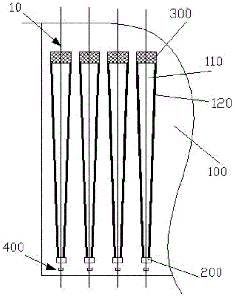
[0013] Below in conjunction with accompanying drawing and embodiment the present invention is further described:

[0014] In this example, see figure 1 The broken yarn capture device of the loom comprises a capture platform 100, the capture platform 100 is arranged in parallel on one side of the warp yarn 10 transmission plane, and the warp yarn 10 is provided with a tablet sensor 400 for monitoring whether the warp yarn 10 is broken, and each Each of the warp yarns 10 is correspondingly provided with a capture groove 110 on the capture platform 100, and the two ends of the capture groove 110 are respectively provided with an air nozzle 200 and an air suction port 300, and the air jet direction of the air nozzle 200 is consistent with the The transmission direction of the warp yarn 10 is the same, the air jet volume of the air nozzle 200 is equal to the air suction volume of the air suction port 300, and the tablet pressing sensor controls the air nozzle 200.

[0015] In the ...


PUM


Abstract

The invention provides a weaving machine broken yarn catching device. The weaving machine broken yarn catching device comprises a catching platform which is arranged on one side of a warp yarn conveying plane in parallel, warp yarns are provided with presser sensors for monitoring whether the warp yarns are broken, each warp yarn is correspondingly provided with a catching groove in the catching platform, the two ends of each catching groove are provided with an air nozzle and an extraction opening, the spraying direction of each air nozzle is consistent with the conveying direction of the warp yarns, the spraying quantity of each air nozzle is equal to the extraction quantity of the corresponding extraction opening, and a presser controls each air nozzle. According to the weaving machine broken yarn catching device, pressure intensity on one side of each warp yarn is reduced by means of air flow sprayed through the corresponding air nozzle, the broken yarns enter the catching grooves by being sucked by the air flow, and meanwhile tension of the warp yarns is kept by means of friction between the air flow and the weft yarns and the warp yarns are prevented from flying.

Description

Technical field [0001] The invention relates to the field of textile machinery, in particular to a broken yarn capture device suitable for looms. Background technique [0002] The looms are all equipped with a warp break self-stop device, the purpose of which is to detect warp break and send a stop signal. Their types: photoelectric (far-infrared detection), stop-and-go rack, carding and rotating. At present, the stop frame type is mostly used, and its working principle: the stop frame is installed between the back beam and the heald frame, and there are several rows of stop bars on it. The warp stop strip is a combination of inner and outer conductors separated by a thick plastic film to form an open circuit. Many warp stop pieces are set on the warp stop strip, and each warp yarn passes through a warp stop piece alone. When the loom is running, the warp yarn tension will pull up the warp stop piece so that it does not contact with the inner conductor of the warp stop pie...

Claims


Application Information

Patent Timeline
Patent Type & Authority Patents(China)
IPC IPC(8): D03J1/02D03D51/22
Inventor 沈志平
Owner HUZHOU RUNYUAN SILK
Features
  • R&D
  • Intellectual Property
  • Life Sciences
  • Materials
  • Tech Scout
  • Unparalleled Data Quality
  • Higher Quality Content
  • 60% Fewer Hallucinations
Learn More