Clothes dryer and drying method thereof

A technology for clothes dryers and drying cylinders, applied in the field of washing machines, which can solve the problems of less shortened time, less obvious effects, and low drying efficiency, and achieve the effects of saving heating time, reducing energy consumption, and preventing safety accidents

Active Publication Date: 2014-05-28
QINGDAO HAIER WASHING MASCH CO LTD
View PDF9 Cites 11 Cited by
  • Summary
  • Abstract
  • Description
  • Claims
  • Application Information

AI Technical Summary

Problems solved by technology

But this method can only use part of the heat energy of the steam generated in the dryer, the drying efficiency is low, the shortened time is less, and the effect is not obvious

Method used


Image

  • Clothes dryer and drying method thereof
  • Clothes dryer and drying method thereof
  • Clothes dryer and drying method thereof

Examples


specific Embodiment 1

[0047] An embodiment of the present invention provides a clothes dryer, figure 2 is a structural diagram according to an embodiment of the present invention,

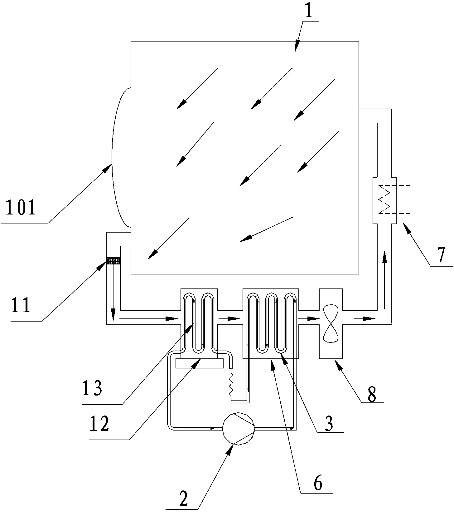
[0048] Such as figure 2 As shown, this embodiment includes: a drying cylinder 1 , an air compressor 2 , a condenser 3 , a water vapor separator and a drainage device 4 , and a heating wire 7 .

[0049] The exhaust end of the drying cylinder 1 described in this embodiment is connected to the intake end of the air compressor 2, and the exhaust end of the air compressor 2 is connected to the intake end of the condenser 3, The exhaust end of condenser 3 is connected with the inlet end of water-gas separator and drainage device 4, the inlet end of preheating pipe 6 is connected with the exhaust end of water-gas separator and drain device 4 through pipelines, The exhaust end of the preheating pipe 6 is connected with the inlet end of the drying cylinder 1 through a heating wire 7 . The condenser 3 is arranged in the preh...

specific Embodiment 2

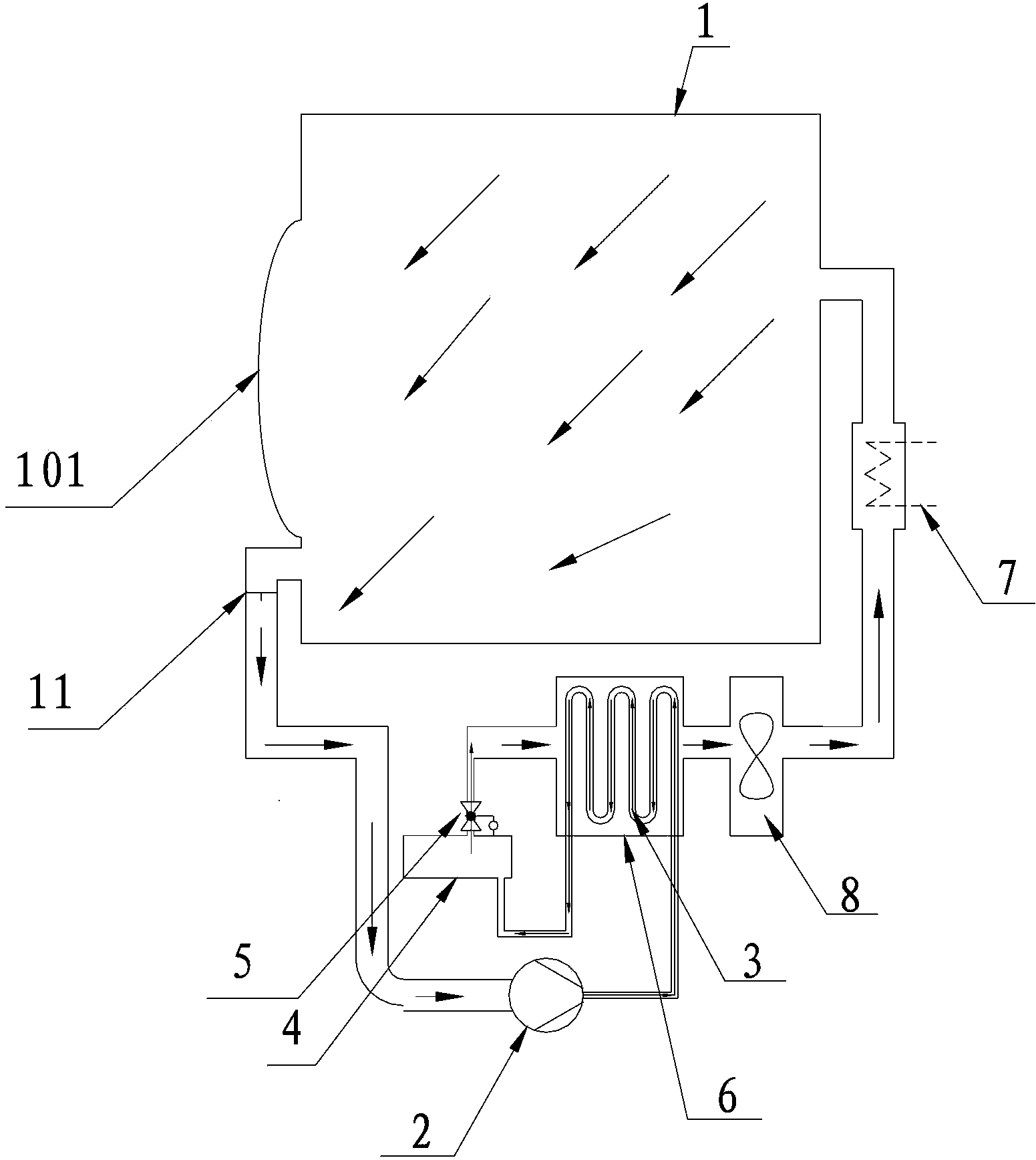
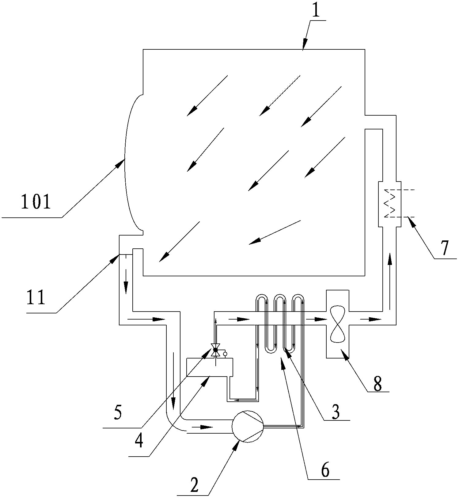
[0058] see Image 6 with Figure 7 As shown, this embodiment includes: a drying cylinder 1 , a condenser 3 , an air compressor 2 , a water vapor separator and a drainage device 4 , and a heating wire 7 .

[0059] The exhaust end of the drying cylinder 1 described in this embodiment is respectively connected to the air compressor 2 and the inlet end of the pipe to be heated 6 through the air passage valve 9, and the air passage valve 9 is connected to the control device 10, The exhaust end of the air compressor 2 is connected with the intake end of the condenser 3, and the exhaust end of the condenser 3 is connected with the intake end of the water-gas separator and the drainage device 4, and the preheating pipe 6 The inlet end of the air inlet is connected with the exhaust end of the water-gas separator and the drainage device 4 through a pipeline, and the exhaust end of the preheating pipe 6 is connected with the inlet end of the drying cylinder 1 through the heating wire 7 ...


PUM


Abstract

The invention discloses a clothes dryer and a drying method thereof. An air incoming end of a condenser arranged on the clothes dryer is connected with an air exhausting end of a drying barrel, an air exhausting end of the condenser is connected with an air incoming end of the drying barrel, an air compressor is arranged arranged on a pipeline between the condenser and the air exhausting end of the drying barrel, a heating wire is arranged on a pipeline between the air exhausting end of the condenser and the air incoming end of the drying barrel, a to-be-heated pipe is arranged between the air incoming end of the condenser and the heating wire, and the condenser is arranged inside the to-be-heated pipe. Through the clothes dryer and the drying method thereof, the problem that drying time is prolonged when energy consumption of a clothes dryer in the prior art is lowered is solved, so that effect of reducing power consumption and drying time of the clothes dryer is realized.

Description

technical field [0001] The invention relates to a clothes dryer and a drying method thereof in the field of washing machines. Background technique [0002] According to the way of heat source, the existing clothes dryers are divided into two ways: heating and drying by heating tubes and drying by using heat pump to absorb the residual heat of hot and humid air in the cylinder. Drying by heating tubes can be divided into direct discharge and water condensation. and air condensing methods, figure 1 It is a structural diagram of a heat pump drying tumble dryer according to the prior art, such as figure 1 As shown, the structure of the clothes dryer in the prior art is as follows: a rotating cylinder is provided in the casing, and a clothes input port is provided in front of the rotating cylinder, which can be opened / closed. An air circulation channel is arranged inside the casing, and the air circulation channel includes a drying cylinder, a lint filter, a heat pump mechanism...

Claims


Application Information

Patent Timeline
Patent Type & Authority Applications(China)
IPC IPC(8): D06F58/02D06F58/04D06F58/26D06F58/28
CPCD06F58/02D06F58/20D06F58/30D06F58/38D06F58/50D06F2103/08D06F2103/36D06F2105/24
Inventor 许升宋华诚田书君单世强
Owner QINGDAO HAIER WASHING MASCH CO LTD
Why Eureka
Try Eureka