Water discharging device with cleaning function

A water outlet device and functional technology, applied in the field of water outlet devices, can solve the problems of complex structure and large space occupation, and achieve the effects of high deformation sensitivity, small space occupation, stable and reliable deformation

Active Publication Date: 2014-05-28
XIAMEN SOLEX HIGH TECH IND CO LTD
View PDF7 Cites 8 Cited by
  • Summary
  • Abstract
  • Description
  • Claims
  • Application Information

AI Technical Summary

Problems solved by technology

When the valve is closed, the impurity particles are filtered through the filter screen, and the impurity particles are stored on the filter screen; when the valve is opened, the water flow carries the impurity particles and is discharged from the bypass channel or cleaning

Method used


Image

  • Water discharging device with cleaning function
  • Water discharging device with cleaning function
  • Water discharging device with cleaning function

Examples


Embodiment 1

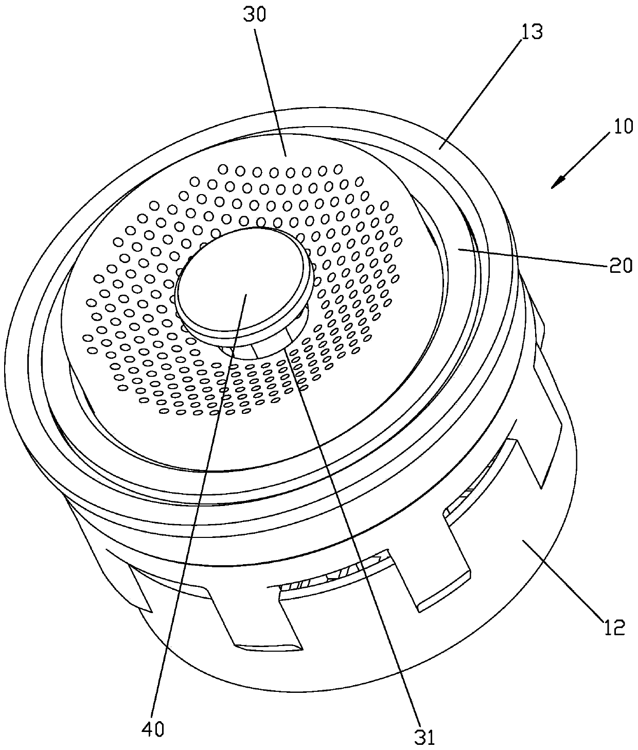
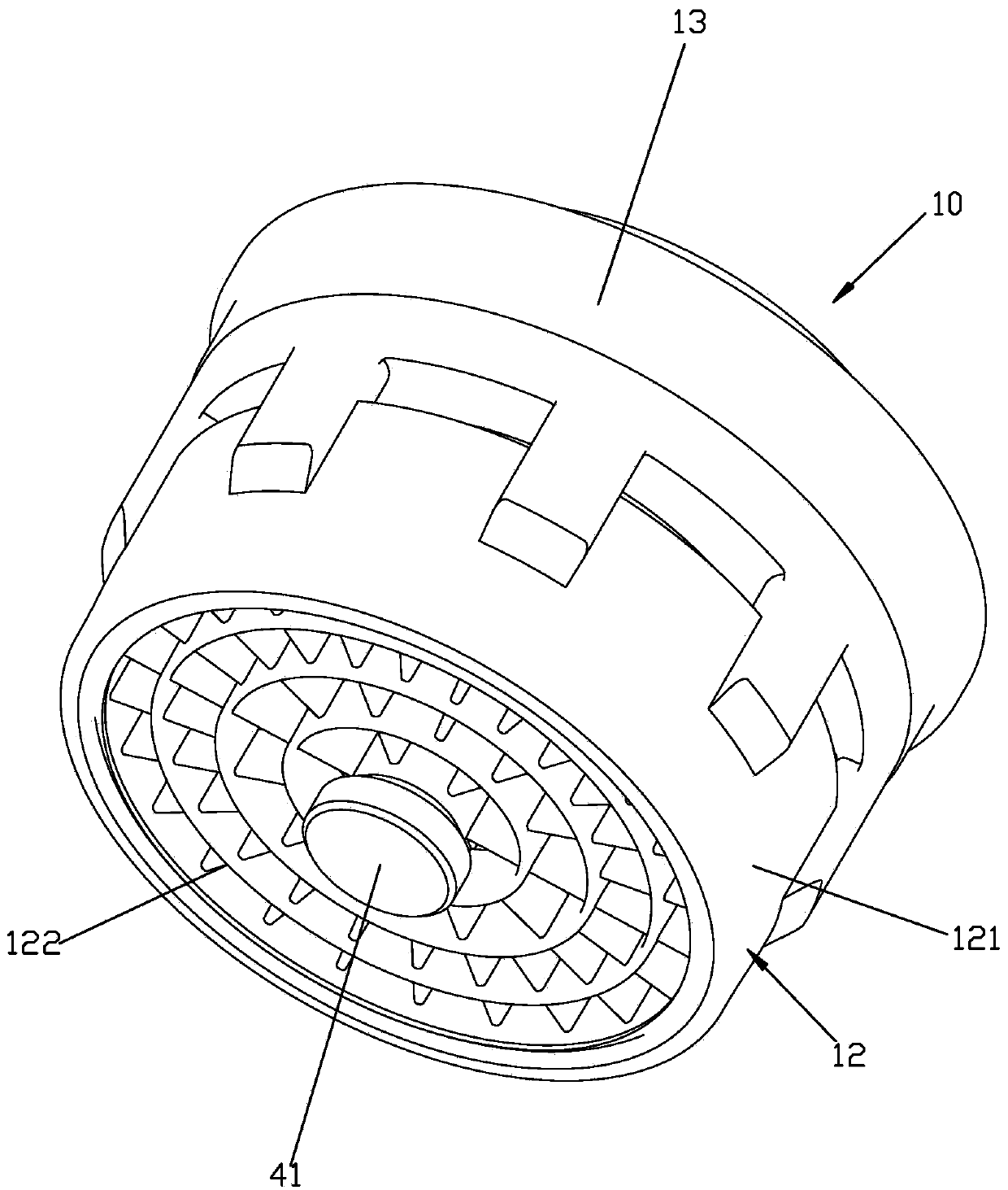
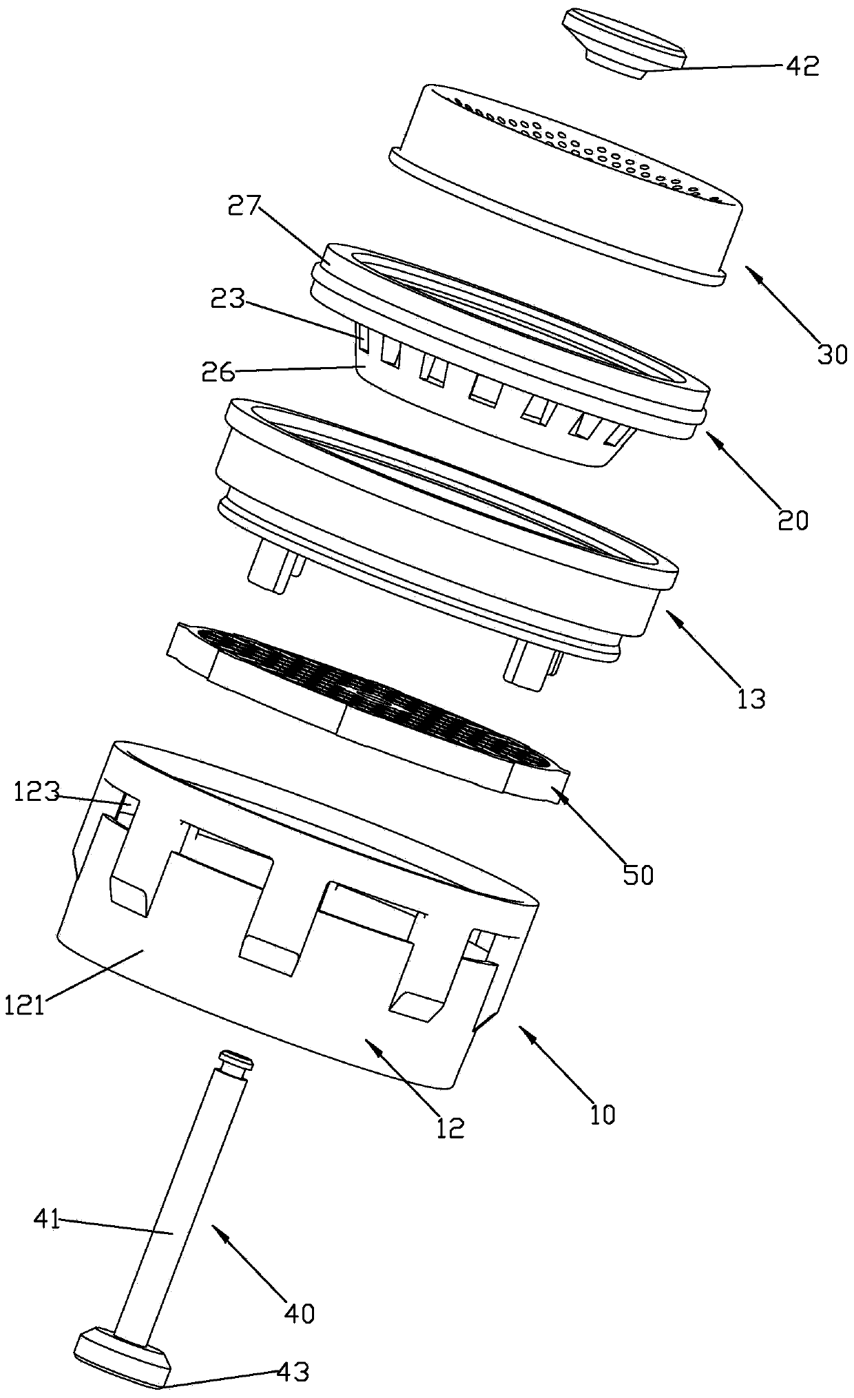
[0055] Please check Figure 1 to Figure 6 , a water outlet device with a cleaning function, including a body part 10 , a diverter 20 , a filter 30 , a rectifier 50 and a sewage channel 80 .

[0056] The body part 10 is provided with a mounting through hole 11 . In this embodiment, the body part 10 includes a body 12 and a fixing ring 13 . The body 12 includes a sleeve body 121 and a grid seat 122 fixed in the sleeve body 121. The fixing ring 13 and the sleeve body 121 are connected together by clamping so that the fixing ring 13 is fixedly mounted on the body. within 12. The specific attachment structure of the fixed ring 13 and the sleeve body 121 is, for example: the outer rotating surface of the fixed ring 13 is set as a stepped rotating surface and has a downward annular surface, and the outer rotating surface of the fixed ring 13 and the sleeve body 121 The inner walls are connected together by buckles. The buckles include a ring groove on the inner wall of the sleeve ...

Embodiment 2

[0065] Please check Figure 7 , It differs from Embodiment 1 in that: the sealing member 42 is adapted to the inner wall of the sewage through hole 31, and an impurity particle storage tank 70 is formed between the sealing member and the sewage through hole 31 in the sealed state.

Embodiment 3

[0067] Please check Figure 8 , it differs from Embodiment 1 in that: the sealing portion 40 includes a solid rod 46 fixed to the center of the bottom wall of the diverter 20 and a sealing valve plate 47 capable of sealing the sewage through hole 31, the sealing valve plate 47 Fixed on the top of the solid rod 46, the sealing valve plate 47 can be deformed by water pressure, and the sealing part 40 is controlled to be in a clean state or a sealed state through the deformation of the sealing valve plate 47.

[0068] When the water pressure is high, the sealing valve plate 47 deforms greatly, and the peripheral edge of the sealing valve plate 47 is sealed against the outside of the sewage discharge through hole. Filter on the filter net and store on the filter net; when the water pressure is small, the deformation of the sealing valve plate 47 is small, there is a gap between the periphery of the sealing valve plate 47 and the sewage through hole, the sewage through hole is open...


PUM


Abstract

The invention discloses a water discharging device with a cleaning function. The water discharging device comprises a body part, a flow divider, a filter screen and a sealed part, wherein the flow divider is arranged in a mounting through hole of the body part and is provided with a bottom wall and a surrounding part which surrounds outside the bottom wall and is provided with a plurality of communicated flow dividing holes; the filter screen is arranged at the front end of the flow divider; one opening of a drain channel is a drain through hole formed in the center of the filter screen, and the other opening of the drain channel is communicated with the flow dividing holes; the sealed part is connected to the flow divider and can be changed between a clean state and a sealed state, and the connection or disconnection of the drain channel is controlled by controlling the sealed part to be in the clean or sealed state. The water discharging device has the advantages that capability of preventing impurity particles from blocking a water outlet nozzle, cleaning the filtered impurity particles and sharing the flow dividing holes, simple and compact structure, relatively small occupied space, low mould opening cost and relatively high rate of finished products.

Description

technical field [0001] The invention relates to a water outlet device with cleaning function. Background technique [0002] During the water discharge process, the water flow of the water supply source must contain some impurity particles. If these impurity particles are not filtered, the impurity particles may block the water outlet of the water outlet device, thereby shortening the service life of the water outlet device and reducing the comfort of use. [0003] Aiming at the above-mentioned deficiencies, someone proposed a solution, such as CN101395323B announced on November 2, 2011 by the China Patent Database, an invention patent titled "Sanitary Embedded Component". It has at least one bypass or rinsing channel, which is associated with a valve, which opens the at least one bypass or rinsing channel in its open position. The built-in element has a sieve with at least one outlet opening, which has a clear opening cross-section that is enlarged compared to the mesh of t...

Claims


Application Information

Patent Timeline
IPC IPC(8): E03C1/02F16K7/12
Inventor 吴石龙赵国松赖灿彬周华松
Owner XIAMEN SOLEX HIGH TECH IND CO LTD
Why Eureka
Try Eureka