
Joint assembly of u-shaped steel-concrete composite beam and rectangular steel tube concrete column

A technology of rectangular steel pipes and concrete columns, applied in the direction of buildings and building structures, can solve the problems of low bearing capacity of nodes, unreasonable connection methods of nodes, insufficient ductility and energy dissipation capacity of the core area of ​​nodes, etc., to achieve high bearing capacity, Easy to build and decorate, reasonable stress effect

Active Publication Date: 2016-09-07
JIANGSU ZHONGBAO STEEL STRUCTURE
View PDF6 Cites 0 Cited by
  • Summary
  • Abstract
  • Description
  • Claims
  • Application Information

AI Technical Summary

Problems solved by technology

[0003] The purpose of the present invention is to solve the problem that the connection mode of the existing nodes is unreasonable, which leads to the low bearing capacity of the nodes, insufficient ductility and energy dissipation capacity of the core area of ​​the nodes, so that the nodes are destroyed before other components, and then provides a U Joint components of steel-concrete composite beams and rectangular concrete-filled steel tube columns

Method used


Image

  • Joint assembly of u-shaped steel-concrete composite beam and rectangular steel tube concrete column
  • Joint assembly of u-shaped steel-concrete composite beam and rectangular steel tube concrete column
  • Joint assembly of u-shaped steel-concrete composite beam and rectangular steel tube concrete column

Examples


specific Embodiment approach 1

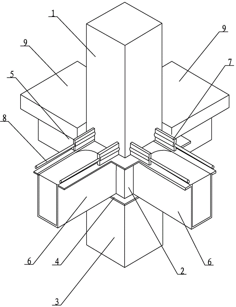
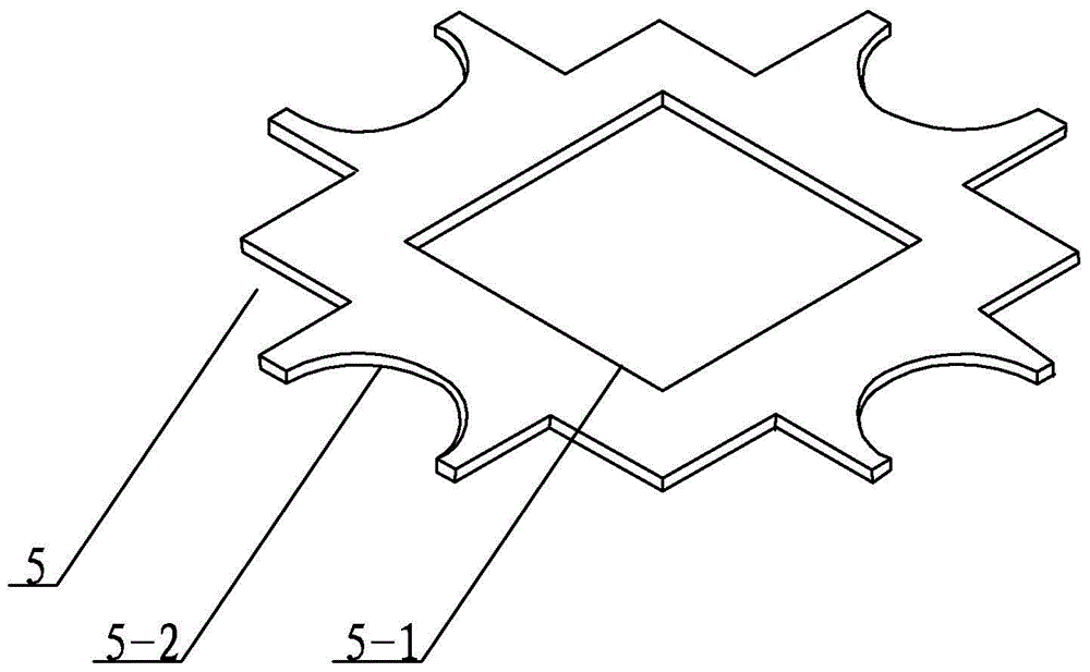
[0013] Embodiment 1: Combining Figure 1-Figure 4 Illustrating this embodiment, the node assembly of the U-shaped steel-concrete composite beam and the rectangular steel tube concrete column in this embodiment includes a first rectangular steel tube 1, a second rectangular steel tube 2, a third rectangular steel tube 3, and a partition plate 4 in the node area. , node area reinforcement ring 5, four U-shaped steel beams 6, multiple concrete slabs 9, multiple node area plug-in panels 7 and multiple steel bars 8 with the same number as the plug-in panels 7, the first rectangular steel pipe 1, the second rectangular The steel pipe 2 and the third rectangular steel pipe 3 are arranged in sequence from top to bottom, the partition plate 4 is fixedly arranged between the second rectangular steel pipe 2 and the third rectangular steel pipe 3 in the node area, and the reinforcing ring 5 in the node area is fixedly arranged on the first rectangular steel pipe 1 and the second rectangul...

specific Embodiment approach 2

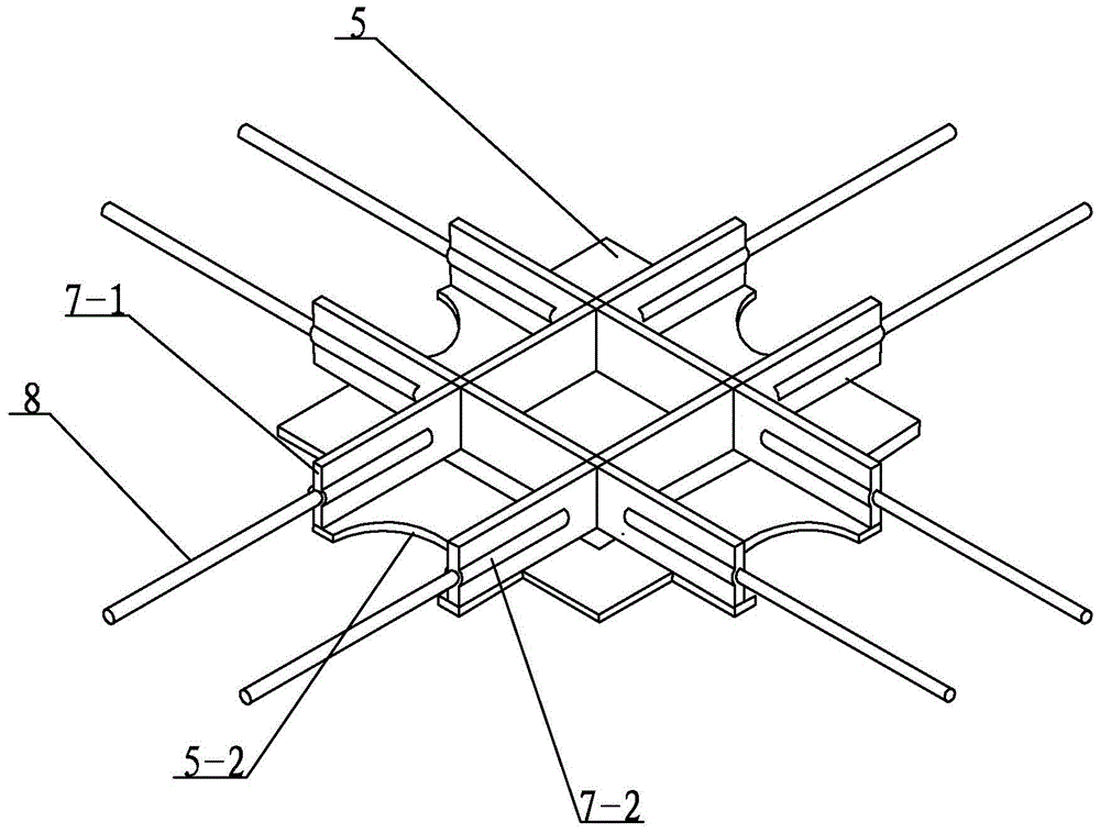
[0020] Specific implementation mode 2: Combining figure 1 and figure 2 Illustrating this embodiment, each node area plug-in board 7 in this embodiment includes a board body 7-1 and two threaded circular sleeves 7-2, and two ends of the board body 7-1 are respectively provided with a belt There is a threaded circular sleeve 7-2, and the threaded circular sleeve 7-2 is arranged along the length direction of the plate body 7-1. This arrangement facilitates the connection between the threaded circular sleeve 7-2 and the steel bar 8, facilitates the connection at the construction site, and speeds up the construction speed. Other components and connection relationships are the same as in the first embodiment.

specific Embodiment approach 3

[0021] Specific implementation three: combination figure 1 and figure 2 Describing the present embodiment, each node area plugboard 7 and a steel bar 8 are connected by screws in the present embodiment. This arrangement facilitates installation and disassembly. Other compositions and connection relationships are the same as in the first or second embodiment.


PUM


Abstract

The invention provides a node assembly of a U-shaped steel-concrete composite beam and a rectangular steel tube concrete column, and relates to a node assembly of a steel tube concrete column. The node assembly of the U-shaped steel-concrete composite beam and the rectangular steel tube concrete column solves the problem that an existing node connection mode is unreasonable, the bearing capability of a node is too low, the ductility and energy-dissipating capacity of the core region of the node is insufficient, and therefore the node is damaged before other component. According to the node assembly of the U-shaped steel-concrete composite beam and the rectangular steel tube concrete column, a first rectangular steel tube, a second rectangular steel tube and a third rectangular steel tube are sequentially arranged from top to bottom, a node region inside partition plate is fixedly arranged between the second rectangular steel tube and the third rectangular steel tube, a node region reinforcing ring is fixedly arranged between the first rectangular steel tube and the second rectangular steel tube, four U-shaped steel beams are evenly distributed on four outer end faces of the second rectangular steel tube, a plurality of node region inserting plates are arranged on the node region reinforcing ring in the shape like a Chinese character 'jing', a steel bar is inserted in each node region inserting plate, and concrete is poured into the interior and the upper portion of each U-shaped steel beam. The node assembly of the U-shaped steel-concrete composite beam and the rectangular steel tube concrete column is used in constructional engineering.

Description

technical field [0001] The invention relates to a node assembly of a concrete-filled steel tube column, in particular to a node assembly of a U-shaped steel-concrete composite beam and a rectangular concrete-filled steel tube column, belonging to the technical field of building structures. Background technique [0002] U-shaped steel-concrete composite beam is a new type of composite member. U-shaped steel is used to replace the I-section steel in traditional composite beams, which can significantly improve the fire resistance, bending stiffness and overall stability of composite beams in the negative bending moment area of ​​the composite beam. Therefore, it has broad development prospects in practical engineering. At present, rectangular CFST columns have been widely used in practical projects. Compared with pure steel components, rectangular CFST columns can significantly reduce the amount of steel used, reduce the structural cost, and improve the fire resistance of steel...

Claims


Application Information

Patent Timeline
Patent Type & Authority Patents(China)
IPC IPC(8): E04B1/58
Inventor 郭兰慧周国平
Owner JIANGSU ZHONGBAO STEEL STRUCTURE
Learn More