Vibration targeting control device for multi-span rotor shaft of rotary machine

A technology for rotating machinery and control devices, which is applied in the directions of rotational vibration suppression, non-rotational vibration suppression, and vibration suppression adjustment, which can solve problems such as inability to start and stop normally, and achieve the effect of solving rotor rubbing.

Active Publication Date: 2014-05-28
BEIJING UNIV OF CHEM TECH
View PDF7 Cites 9 Cited by
  • Summary
  • Abstract
  • Description
  • Claims
  • Application Information

AI Technical Summary

Problems solved by technology

[0006] The purpose of the present invention is to provide a multi-span rotor shaft system vibration targeting control device for rotating machinery. For severe vibration caused by balance or rotor rubbing and other faults, it can continuously calculate the position, time and magnitude of the damping force on-line in real time according to the change of the speed and the vibration of each rotor, and then adjust the damper parameters to control the damping The position, time and magnitude of the force form a real-time continuous closed-loop controllable vibration control to realize the targeted control of the shafting vibration; it has a wide range of applications and a high degree of automation, and can be widely used in actual units

Method used


Image

  • Vibration targeting control device for multi-span rotor shaft of rotary machine
  • Vibration targeting control device for multi-span rotor shaft of rotary machine
  • Vibration targeting control device for multi-span rotor shaft of rotary machine

Examples


Embodiment 1

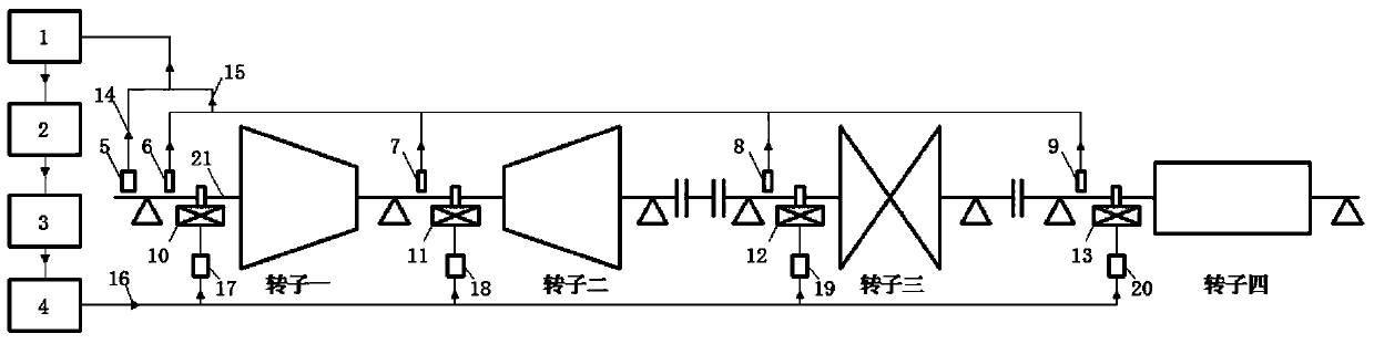
[0045] by figure 2Taking the shafting of the medium generator set as an example, the specific control scheme during the starting process of the shafting is shown in Table 2; the speed increases gradually from 0r / min, and all the magneto-rheological dampers are closed at this time. When the speed reaches about 850r / min min, the control signal 16 controls the adjustable power supply D20 to turn on the magneto-rheological damper D13; when the speed reaches about 1150r / min, the control signal 16 controls the adjustable power supply 20 to turn off the magneto-rheological damper D13; when the speed reaches about At 1275r / min, the control signal 16 controls the adjustable power supply B18 to turn on the magneto-rheological damper B11; when the speed reaches about 1658r / min, the control signal 16 controls the adjustable power supply A17 to turn on the magneto-rheological damper A10; When the speed reaches about 1725r / min, the control signal 16 controls the adjustable power supply B18...

Embodiment 2

[0051] by figure 2 Taking the mid-span rotor shaft system as an example, the specific control scheme during the shaft shutdown process is shown in Table 2. The speed gradually decelerates from 3000r / min, and the adjustable power supply D20 is controlled to turn on the magneto-rheological damper D13, and the other dampers are turned off; when the speed reaches about 2358r / min, the adjustable power supply C19 is controlled to turn on the magneto-rheological damper C12; When the rotating speed reaches about 2253r / min, control the adjustable power supply D20 to close the magnetorheological damper D13; when the rotating speed reaches about 2243r / min, control the adjustable power supply A17 to turn on the magnetorheological damper A10; when the rotating speed reaches about At 1743r / min, control the adjustable power supply C19 to turn off the magnetorheological damper C12; when the speed reaches about 1725r / min, control the adjustable power supply B18 to turn on the magnetorheologic...

Embodiment 3

[0055] by figure 2 Take the mid-span rotor shafting system as an example. When the shafting system runs on a certain span or several spans of the rotor due to blade breakage, dust accumulation, etc. due to unbalanced faults, the time domain, frequency domain and axis trajectory of the rotor vibration It has certain characteristics; the real-time online signal monitoring and analysis system in the present invention will make judgments based on these characteristics, determine the position of the rotor where the unbalanced fault occurs, and control the opening of the magneto-rheological damper on the corresponding rotor, and give an appropriate working current. Assuming that the rotor 1 of the shaft system vibrates violently due to rotor wear during operation, the real-time online signal monitoring and analysis system determines that the rotor with severe vibration is rotor 1 based on the collected vibration data across the rotors. After system analysis and calculation, the req...


PUM


Abstract

The invention relates to a vibration targeting control device for a multi-span rotor shaft of a rotary machine, and belongs to the technical field of vibration control. By the adoption of the device, the vibration parameter change of the shaft is monitored in real time, the reason of the fault vibration is analyzed, a proper position is determined, proper damping force is applied at the proper time, and thus the vibration targeting control of the shaft is realized. The device comprises a real-time on-line signal monitoring and analyzing system and an execution system, wherein the real-time on-line signal monitoring and analyzing system comprises an eddy current displacement sensor, a photoelectric sensor, a signal conditioning module, a data collecting card, an analog output module and a computer; the execution system comprises a magnetorheological damper and an adjustable power supply. The device mainly solves the problems that the vibration is greater when the shaft is started and stopped to pass through each critical rotation speed, and the severe vibration is generated by the rubbing during the operation, by the sudden imbalance and the like.

Description

technical field [0001] The invention relates to a multi-span rotor shaft system vibration targeting control device for a rotating machine, which belongs to the technical field of vibration control. Background technique [0002] Many large-scale rotating equipment in the fields of energy and petrochemicals generally adopt the form of multi-axis series operation, such as turbo-generator units, compressor units, etc. After the rotors of the unit are strictly dynamically balanced, the residual unbalance is within the allowable range, and then the rotors are assembled in series. After running, it is found that the shafting may still vibrate strongly, resulting in failure to start the machine normally. At present, the method of on-site dynamic balancing is usually used to eliminate the unbalanced vibration of the shaft system, but this method needs to start and stop the unit repeatedly several times or even dozens of times, and the economic loss is serious. [0003] In addition t...

Claims


Application Information

Patent Timeline
Patent Type & Authority Applications(China)
IPC IPC(8): F16F15/32F16F15/10F16F9/53
Inventor 何立东王锎邢健黄秀金高金吉
Owner BEIJING UNIV OF CHEM TECH
Why Eureka
Try Eureka