
Complicated equipment acoustic fault recognition and location method

A technology of fault identification and positioning method, which is applied in the testing of measuring devices, instruments, machinery/structural components, etc. It can solve the problem of serious coupling of equipment components, difficult signal processing and analysis techniques, and the uncertainty of detection information of single-point sensors. And other issues

Inactive Publication Date: 2014-05-28
BEIJING UNIV OF POSTS & TELECOMM
View PDF4 Cites 25 Cited by
  • Summary
  • Abstract
  • Description
  • Claims
  • Application Information

AI Technical Summary

Problems solved by technology

[0004] Although some research results have been achieved in equipment fault diagnosis, there are still some problems as follows: 1) Due to the increasingly complex structure of equipment and the serious coupling between equipment components, it is difficult to identify and locate equipment faults by establishing an accurate mathematical model ; 2) Most of the existing fault identification methods use a single parameter or standard for diagnosis, and the reliability is poor. At the same time, the advanced online monitoring system imported from abroad is relatively expensive
[0005] Affected by factors such as noise, time-varying effects, and environmental changes, the detection information of a single-point sensor has uncertainty and ambiguity
For increasingly complex mechanical equipment systems, it is often necessary to deploy multiple measuring points for distributed network monitoring, and its detection information shows formal uncertainty, diversity, huge quantity and complexity of relationships. Traditional Signal processing and analysis techniques are difficult to deal with effectively

Method used


Image

  • Complicated equipment acoustic fault recognition and location method
  • Complicated equipment acoustic fault recognition and location method
  • Complicated equipment acoustic fault recognition and location method

Examples


Embodiment Construction

[0058] The present invention will be further described in detail below in conjunction with the accompanying drawings.

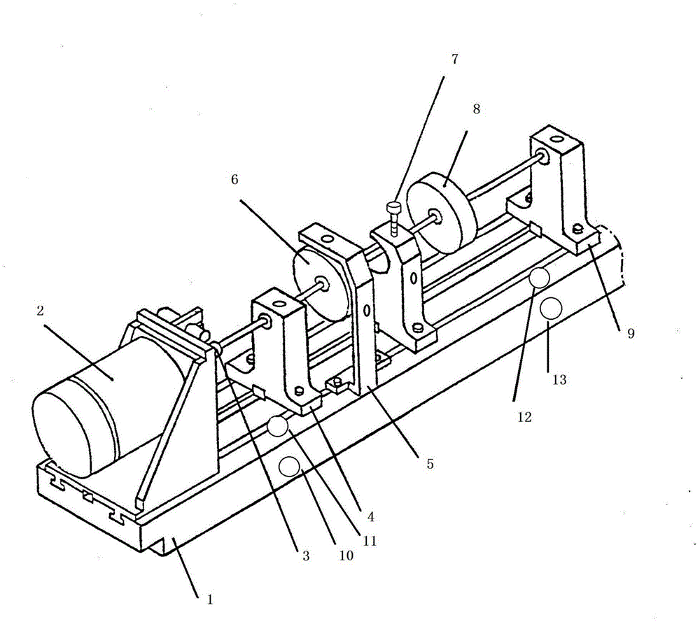
[0059] figure 1 The structure of the ZT-3 rotor vibration simulation test bench is given. It is 1200mm long, 108mm wide, 145mm high, and has a mass of about 45kg. The diameter of the rotating shaft is Ф9.5mm, and the diameter of the rotor is 76mm. 2), coupling (3), inner bearing seat (4), eddy current sensor support (5), rotor I (6), friction screw and support (7), rotor II (8), outer bearing seat (9) ; Deploy 4 Lance2052 acceleration sensors around the rotor table, sensor A (10) on the side of the proximal base of the motor side, sensor B (11) directly above the proximal base of the motor side, and sensor directly above the distal base of the motor side C (12), the sensor D (13) on the side of the base at the far end of the motor side, measures the vibration signals of the rotor equipment in the horizontal and vertical directions respectively; the experimen...


PUM


Abstract

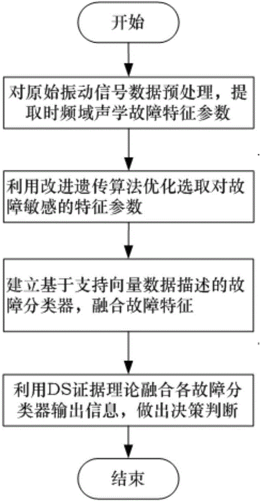
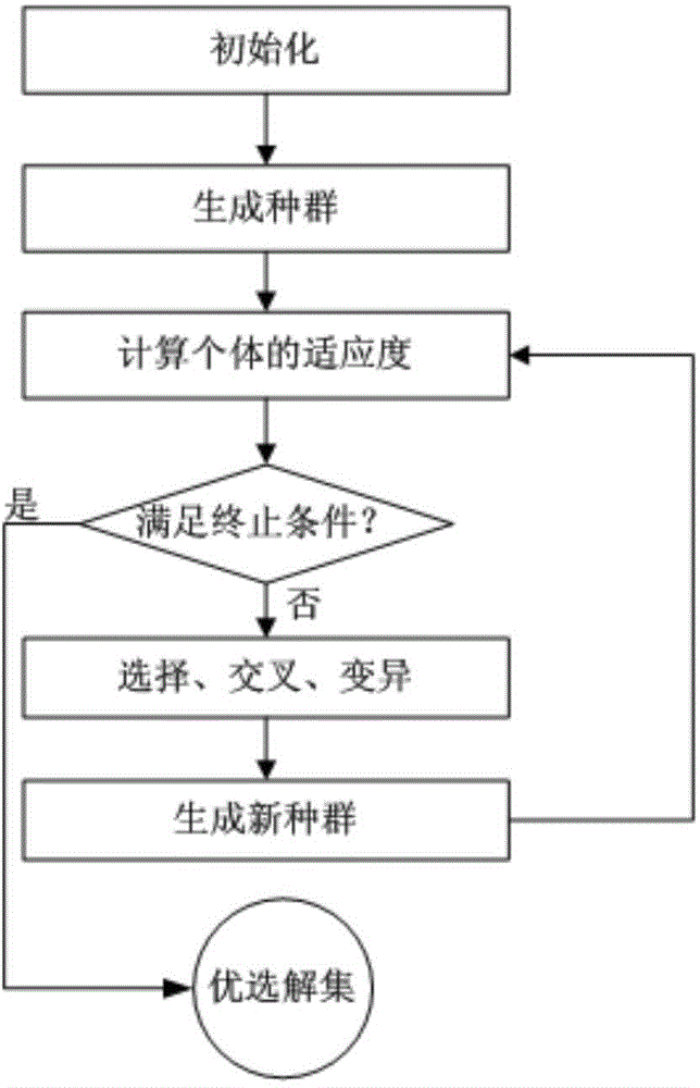
The invention discloses a complicated equipment acoustic fault recognition and location method. The method comprises steps of carrying out data pre?processing and fault feature extraction on vibration signals of a single sensor in a distributed equipment monitoring network, using a within-class between-class distance as an evaluation function of genetic algorithm and optimally selecting characteristic parameters sensitive to a fault, building single-value classifier?models based on support vector data description for initial fault recognition through training a normal class sample set, and constructing a basic probability?assignment?function of?an evidence according to output information of fault classifiers of different measurement points, adopting an evidence combination rule to combine an evidence set and making a decision result. The invention provides an equipment acoustic fault recognition and location method with vibration information hierarchically-converged, a recognition technology in a multi-feature comprehensive analysis mode is adopted, vibration information of different measurement points is made full use of, a strong generalization ability is provided, and the problem that precise mathematical?modeling is hard to be built for fault recognition and location due to complicated structure of the equipment can be solved.

Description

technical field [0001] The invention relates to the technical field of acoustic fault diagnosis of mechanical equipment, in particular to an acoustic fault identification and positioning method for complex equipment in a distributed monitoring network. Background technique [0002] With the rapid development of science and technology, various types of machinery and equipment in industrial and mining enterprises such as electric power, transportation, and mining, such as water pumps, internal combustion engines, turbines, fans, and chemical equipment, are moving towards large-scale, complex, high-speed, and automated development. The interconnection and coupling between different parts of the equipment are getting closer and closer. Often a small failure of one part will cause a chain reaction, ranging from reduced production efficiency and equipment downtime, to serious accidents such as machine crashes and fatalities, which will seriously affect people's lives, Property and...

Claims


Application Information

Patent Timeline
IPC IPC(8): G01M99/00
Inventor 陈斌高宝成张斯婕
Owner BEIJING UNIV OF POSTS & TELECOMM
Learn More