
Insulation resistance detecting device for high-voltage circuit

A high-voltage circuit, insulation resistance technology, applied in measuring devices, measuring resistance/reactance/impedance, measuring electricity, etc., can solve problems such as damage to electrical appliances, influence of detection objects, burns, etc., to achieve the effect of simple structure

Inactive Publication Date: 2014-05-28
CHINA NORTH VEHICLE RES INST
View PDF6 Cites 5 Cited by
  • Summary
  • Abstract
  • Description
  • Claims
  • Application Information

AI Technical Summary

Problems solved by technology

If leakage occurs, it may cause damage to electrical appliances, spontaneous combustion of electric vehicles, or even burns or injuries to the human body; how to detect the leakage of high-voltage lines in time is a problem that must be solved in the promotion of electric vehicles
[0003] There are two existing detection methods for detecting the insulation resistance of high-voltage circuits, namely the AC method and the non-insulated DC method. The AC method detects the leakage resistance by applying a signal to the vehicle body target, and uses capacitors and transformers to insulate the vehicle body from the DC current. For example, the patent application number 200680025396.9 provides a method for detecting leakage using an AC signal; the non-insulated direct current method does not use capacitors and transformers, but applies leakage resistance to direct current to measure leakage conditions, such as the patent application number 200510073896.7 provides a method for measuring leakage resistance, but the disadvantage of these two existing leakage detection methods is that the detection circuit is connected with the detection object, which will have an impact on the detection object

Method used


Image

  • Insulation resistance detecting device for high-voltage circuit
  • Insulation resistance detecting device for high-voltage circuit
  • Insulation resistance detecting device for high-voltage circuit

Examples


Embodiment

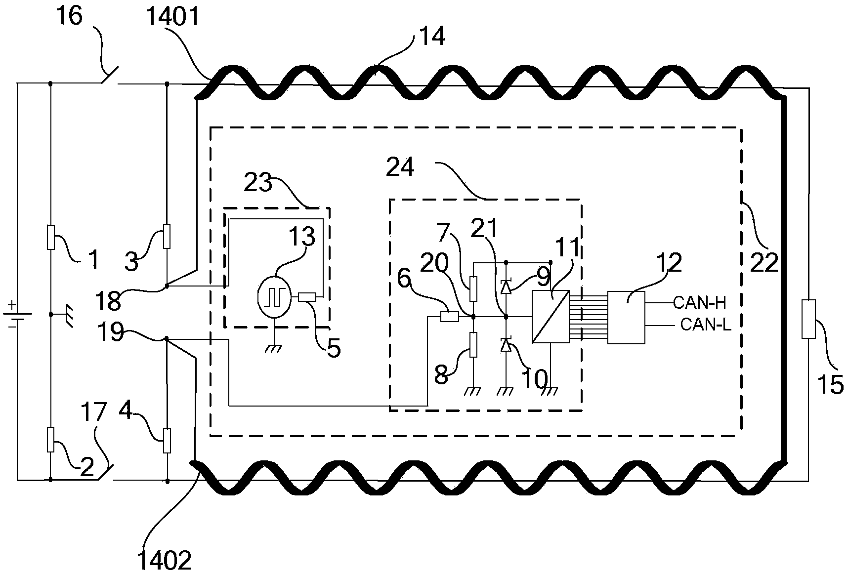
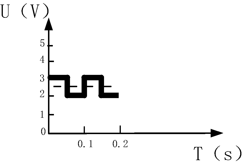
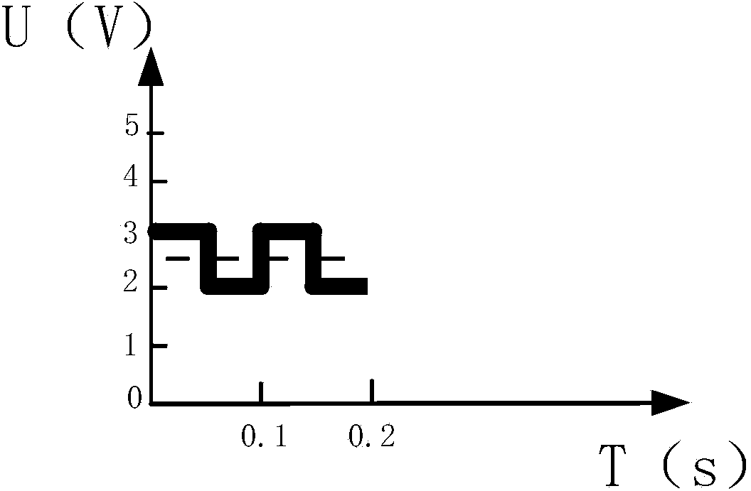
[0067] In the high-voltage circuit insulation resistance detection device proposed in this embodiment, the first resistor 1, the second resistor 2, the third resistor 3 and the fourth resistor 4 are all 660kΩ resistors, the fifth resistor 5, the sixth resistor 6, Both the seventh resistor 7 and the eighth resistor 8 are 100kΩ resistors. The first zener diode 9 and the second zener diode 10 select the IN4733 model, the breakdown voltage is 5.1V, and the induction strip 14 is a H62 copper strip with a thickness of 0.8mm, a width of 30mm, and a length of 5m. The number of winding turns is 100 turns. The diagnostic signal sent by the signal generator 13 is a square wave signal with a valley voltage of 2V and a peak voltage of 3V. Both the signal generator 13 and the signal receiver 11 are driven by an external power supply of 5V.

[0068] Engage the first switch 16 and the second switch 17, so that the diagnostic circuit 22 in the detection device is communicated with the high-vo...


PUM


Abstract

The invention belongs to the technical field of circuit diagnosis, and particularly relates to an insulation resistance detecting device for a high-voltage circuit. The detecting device comprises a first resistor, a second resistor, a third resistor, a fourth resistor, a first switch, a second switch, an induction band and a diagnosis circuit. The diagnosis circuit comprises a diagnosis signal generating circuit, a diagnosis signal receiving circuit and a monitoring unit. The induction band is wound on a high-voltage line, so that the electric leakage condition of a positive electrode or a negative electrode of the high-voltage line and the short circuit condition of the high-voltage line are detected quantificationally, in the electric leakage detecting process, electric leakage information can be sent out to a control system or a display system of an electric vehicle through a CAN line, and thus a prompting function or a warning function can be achieved. According to the electric leakage detecting device and a detecting method thereof, a non-contact detecting method is adopted, and the detected high-voltage line cannot be affected.

Description

technical field [0001] The invention belongs to the technical field of circuit diagnosis, and in particular relates to a high-voltage circuit insulation resistance detection device. Background technique [0002] The DC voltage of the existing electric vehicle storage battery reaches more than 300V. If a leakage occurs, it may cause damage to electrical appliances, spontaneous combustion of electric vehicles, or even burns or injuries to the human body; how to detect the leakage of high-voltage lines in time is a problem that must be solved in the promotion of electric vehicles. [0003] There are two existing detection methods for detecting the insulation resistance of high-voltage circuits, namely the AC method and the non-insulated DC method. The AC method detects the leakage resistance by applying a signal to the vehicle body target, and uses capacitors and transformers to insulate the vehicle body from the DC current. For example, the patent application number 200680025...

Claims


Application Information

Patent Timeline
Patent Type & Authority Applications(China)
IPC IPC(8): G01R27/02G01R31/02
Inventor 高峰戚于飞刘胜利李申宋克岭张思宁郑洁袁盛芮蒋任君王坤
Owner CHINA NORTH VEHICLE RES INST
Learn More