Insulator pollution flashover pre-warning method and system based on leakage currents
A leakage current and insulator technology, applied in the direction of testing dielectric strength, etc., can solve the problems of limited frequency range of leakage current signal, inability to reflect the change of insulator leakage current and insulator pollution performance, etc., to achieve fast processing speed, reduce service cost, and facilitate The effect of installation
- Summary
- Abstract
- Description
- Claims
- Application Information
AI Technical Summary
Problems solved by technology
Method used
Image
Examples
Embodiment 1
[0060] An insulator pollution flashover warning system and method based on leakage current. The system mainly includes an LED optical fiber sensor, a signal pre-processing module, a data acquisition module, a GPRS wireless transmission module, a solar-battery power supply module, and a data acquisition extension platform. The method mainly includes data collection method and data analysis method. in,
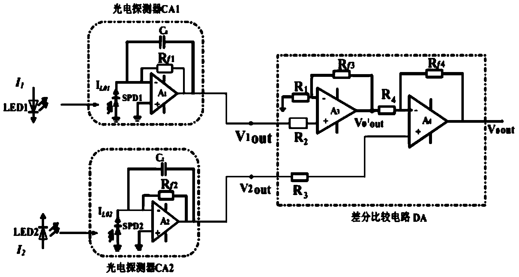
[0061] The LED optical fiber sensor includes a sensor probe and a photoelectric converter.
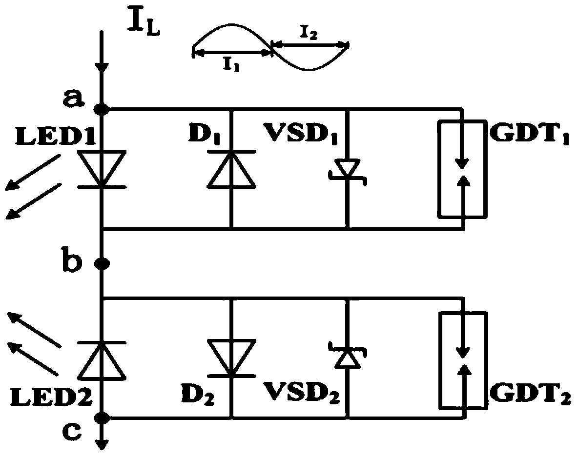
[0062] The sensor head is composed of two light emitting diodes LED1 and LED2 and two protection circuits. The ports of the same polarity of the two light emitting diodes LED1 and LED2 are connected in series to detect the positive and negative half cycle leakage currents of the tested insulator strings respectively. Each protection circuit is composed of a conduction diode D, a constant voltage diode VSD and a discharge tube GDT connected in parallel. The conduction diode D is connec...
Embodiment 2
[0076] Such as figure 1 As shown, the insulator pollution flashover warning system based on leakage current mainly includes LED fiber optic sensor, signal pre-processing module, data acquisition module, GPRS wireless transmission module, solar-battery power supply module, and data acquisition extension platform.
[0077] The LED optical fiber sensor includes a sensor probe and a photoelectric converter.
[0078] The schematic diagram of the sensor head is attached figure 2 As shown, it consists of two light-emitting diodes LED1 and LED2 and two protection circuits. The ports of the same polarity of the two light emitting diodes LED1 and LED2 are connected in series to detect the positive and negative half cycle leakage currents of the tested insulator strings respectively. Each protection circuit is composed of a conduction diode D, a constant voltage diode VSD and a discharge tube GDT connected in parallel. The conduction diode D is connected in parallel with the reverse ...
PUM
 Abstract
Description
Claims
Application Information
 - R&D
- Intellectual Property
- Life Sciences
- Materials
- Tech Scout
- Unparalleled Data Quality
- Higher Quality Content
- 60% Fewer Hallucinations
Browse by: Latest US Patents, China's latest patents, Technical Efficacy Thesaurus, Application Domain, Technology Topic, Popular Technical Reports.
© 2025 PatSnap. All rights reserved.Legal|Privacy policy|Modern Slavery Act Transparency Statement|Sitemap|About US| Contact US: help@patsnap.com


