
Double-light-path leakage current optical fiber sensor device

A fiber optic sensor, leakage current technology, applied in measuring devices, measuring current/voltage, voltage/current isolation, etc., can solve problems such as incomplete signal information, affecting the accuracy of online monitoring, and inability to describe

Inactive Publication Date: 2013-01-30
CHONGQING UNIV
View PDF1 Cites 0 Cited by
  • Summary
  • Abstract
  • Description
  • Claims
  • Application Information

AI Technical Summary

Problems solved by technology

The disadvantage of this current sensor system is that the sensor system uses a light-emitting diode-based sensor probe to collect the leakage current of the insulator string. Since the light-emitting diode has unidirectional conductivity, the sensor can only extract half a cycle of the insulator string leakage current. As a result, the system loses the other half-cycle signal of the leakage current waveform of the measured insulator string during the system detection, and finally the signal information of the detection leakage current is not complete, and it cannot be completely described for the full wave of the leakage current, which affects the online monitoring. Accuracy, cannot meet the high accuracy and high efficiency requirements of electrical equipment in modern power systems

Method used


Image

  • Double-light-path leakage current optical fiber sensor device
  • Double-light-path leakage current optical fiber sensor device
  • Double-light-path leakage current optical fiber sensor device

Examples


Embodiment

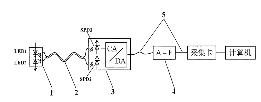
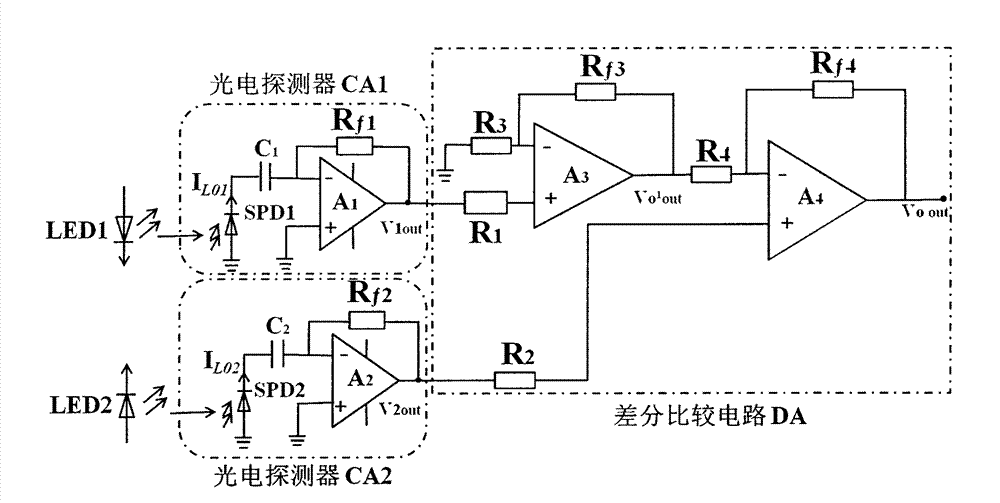
[0057] Such as Figure 1~3 As shown, a dual optical path leakage current optical fiber sensor device mainly includes a fixed bracket, a sensor head 1, an optical fiber 2, a converter 3, a modulator 4, an acquisition card, and a computer. Its characteristics are:

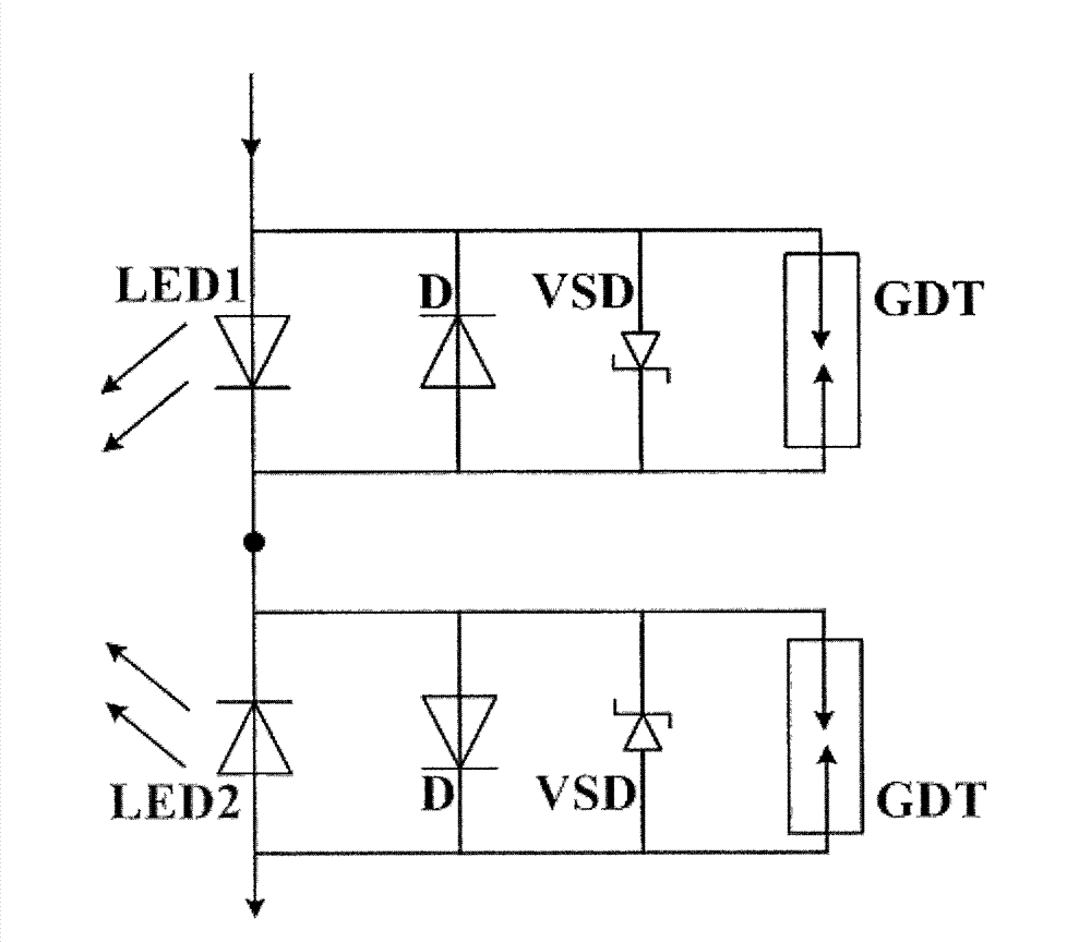
[0058]The sensor head 1 is composed of two light emitting diodes LED1 and LED2 and two protection circuits. The ports of the same polarity of the two light emitting diodes LED1 and LED2 are connected in series to detect the positive and negative half cycle leakage currents of the tested insulator strings respectively. Each protection circuit is composed of a conduction diode D, a constant voltage diode VSD and a discharge tube GDT connected in parallel. Each conduction diode D is connected in parallel with the opposite polarity of the light-emitting diode LED1 or LED2, and is used to guide the half-cycle leakage current that cannot pass through the light-emitting diode. The tube GDT is connected in parallel to pre...


PUM


Abstract

The invention discloses a double-light-path leakage current optical fiber sensor device and belongs to the technical field of monitoring pollution flashover of electric equipment on line. The device comprises a fixed bracket, a sensor head, an optical fiber, a converter, a modulator, an acquisition card and a computer, and is mainly characterized in that: the sensor head consists of two light emitting diodes (LEDs) and two protective circuits, is coupled to silicon photoelectric diodes of two photoelectric detectors of the converter through two optical fibers respectively, and is used for measuring positive and negative half cyclic waves of the leakage current respectively and the positive and negative half cyclic waves of the leakage current are synthesized into a complete full-wave signal by a differential comparison circuit of the converter. The invention has the characteristics that: the device monitors the full wave of an insulator string on line in real time, and has high anti-jamming capability, high safety, and high sensitivity and monitoring accuracy, and is convenient to install, easy and convenient to operate and the like. The device can be widely used for monitoring the full-wave leakage current of the insulator string on line in an alternating current (AC) transmission line for a transformer substation and an overhead transmission line, and particularly applicable to on-line monitoring of the full-wave leakage current of the insulator string in a high-voltage AC line.

Description

technical field [0001] The invention belongs to the technical field of on-line monitoring of pollution flashover of electrical equipment, in particular to a leakage current sensor device for on-line monitoring of insulator strings in substations and overhead transmission lines. Background technique [0002] In recent years, due to the rapid development of electrical equipment status detection technology in power systems, high-precision, high-accuracy, and high-efficiency sensors have come out and been gradually applied to online monitoring of electrical equipment. For transmission lines, pollution flashover of insulator strings has always been a serious threat to the safe operation of power system transmission lines, so preventing pollution flashover of insulator strings is the focus of the power sector to ensure the safe operation of transmission lines. Since the development of pollution flashover is closely related to the leakage current of insulator strings, detecting and...

Claims


Application Information

Patent Timeline
Patent Type & Authority Patents(China)
IPC IPC(8): G01R19/00G01R31/02G01R15/24G01R15/22
Inventor 姚陈果王建李成祥米彦胡建林蒋兴良孙才新
Owner CHONGQING UNIV
Learn More