Light-emitting board welding and fixing device

A technology for fixing devices and light emitting boards, which is applied in welding equipment, auxiliary devices, auxiliary welding equipment, etc., and can solve the problems of LED displacement and low efficiency of processing and welding of light emitting boards

Inactive Publication Date: 2014-06-04
OCEANKING DONGGUAN LIGHTING TECH +2
View PDF0 Cites 30 Cited by
  • Summary
  • Abstract
  • Description
  • Claims
  • Application Information

AI Technical Summary

Problems solved by technology

However, during the soldering process, the PCB board is generally rotated to make the soldering uniform, and the LED on the PCB board is easily displaced when the

Method used


Image

  • Light-emitting board welding and fixing device
  • Light-emitting board welding and fixing device
  • Light-emitting board welding and fixing device

Examples


Embodiment Construction

[0028] In order to facilitate the understanding of the present invention, the present invention will be described more fully below with reference to the associated drawings. Preferred embodiments of the invention are shown in the accompanying drawings. However, the present invention can be embodied in many different forms and is not limited to the embodiments described herein. On the contrary, these embodiments are provided to make the understanding of the disclosure of the present invention more thorough and comprehensive.

[0029] It should be noted that when an element is referred to as being “fixed” to another element, it can be directly on the other element or there can also be an intervening element. When an element is referred to as being "connected to" another element, it can be directly connected to the other element or intervening elements may also be present.

[0030] Unless otherwise defined, all technical and scientific terms used herein have the same meaning as...


PUM


Abstract

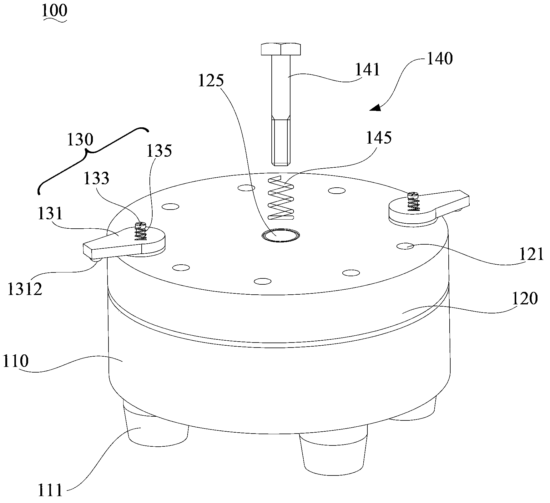
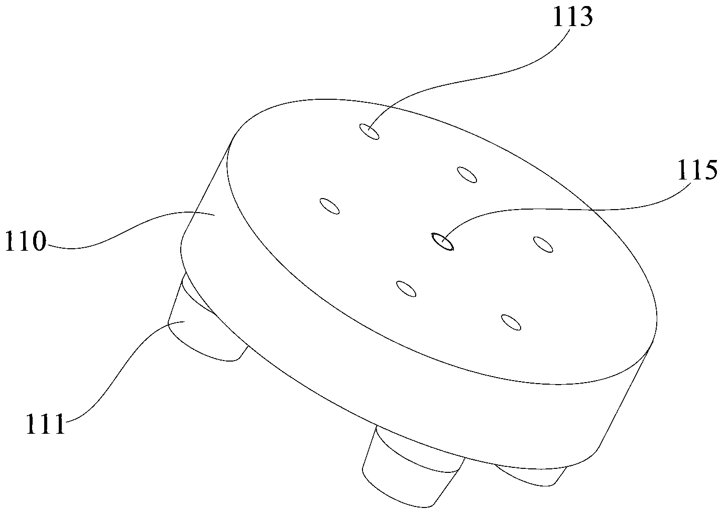
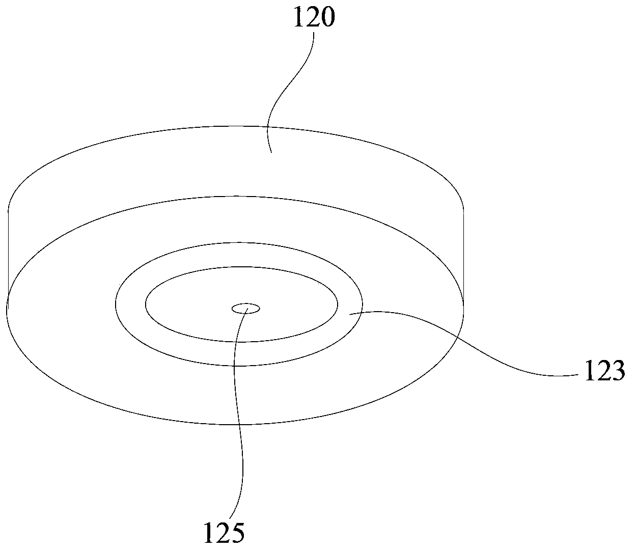
Disclosed is a light-emitting board welding and fixing device. The light-emitting board welding and fixing device comprises a rotary disc, a positioning disc and a buckling assembly, wherein the positioning disc is rotably arranged on the rotary disc. The face, away from the rotary disc, of the positioning disc is a bearing face used for bearing a PCB, and the bearing face is provided with a plurality of poisoning holes, wherein the positioning holes and LEDs can be connected in a clamped mode. When a light-emitting board is manufactured, the LEDs are placed on preset positions of the PCB, the PCB is placed on the positioning disc, and the buckling assembly is rotated to compress the PCB to the positioning disc and clamp the LEDs into the positioning holes. In the welding process, the positioning disc is rotated so that all the LEDs can be welded to the PCB. Because the PCB is compressed to the positioning disc, and the LEDs are clamped into the positioning holes, the LEDs do not move easily in the welding process, operators do not need to position the LEDs again, and welding efficiency is improved.

Description

technical field [0001] The invention relates to a processing technology of a light-emitting board of a lamp, in particular to a welding and fixing device for a light-emitting board. Background technique [0002] With the exploration of new lighting technology, LED (Light Emitting Diode) has gradually become the preferred light source for manufacturing lamps. LEDs have the advantages of low power consumption and low heat generation, but the brightness of a single LED is limited. Therefore, if LEDs are to be used as light sources of lamps, multiple LEDs need to be integrated first to obtain a light-emitting panel with greater brightness. [0003] The light-emitting board of the lamp includes a PCB board (printed circuit board) and a plurality of LEDs welded on predetermined positions on the PCB board. Due to the different shapes and structures of lamps, some light-emitting boards cannot be assembled and welded by large-scale equipment, and need to be assembled by manual weld...

Claims


Application Information

Patent Timeline
IPC IPC(8): B23K37/04
CPCB23K3/087B23K2101/36
Inventor 周明杰陈钢
Owner OCEANKING DONGGUAN LIGHTING TECH
Why Eureka
Try Eureka