Supercharge Your Innovation With Domain-Expert AI Agents!

Sheathing arrangement for a soil-working roller, in particular for a self-propelled soil compactor

A technology of cladding device and compactor, applied in soil protection, infrastructure engineering, roads, etc., can solve time-consuming and labor-intensive problems

Active Publication Date: 2014-06-04
HAMM AG
View PDF5 Cites 0 Cited by
  • Summary
  • Abstract
  • Description
  • Claims
  • Application Information

AI Technical Summary

Problems solved by technology

For this reason, in order to transport a ground compactor with a ground working roller of this configuration, the rolling tools arranged on the outer circumference of the ground working roller, possibly in the range of 150 for example, must be dismantled and replaced on a new one. Using above-ground reassembly, which is very time-consuming and labor-intensive

Method used


Image

  • Sheathing arrangement for a soil-working roller, in particular for a self-propelled soil compactor
  • Sheathing arrangement for a soil-working roller, in particular for a self-propelled soil compactor
  • Sheathing arrangement for a soil-working roller, in particular for a self-propelled soil compactor

Examples


Embodiment Construction

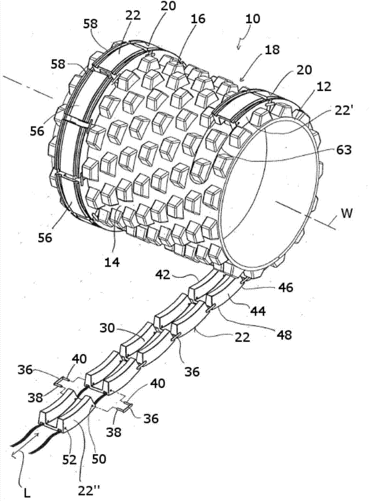
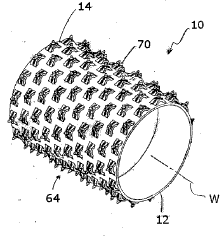
[0031] exist figure 1 shows a ground working roller 10 that can be used, for example, on a self-propelled ground compactor. The floor working roller 10 extending longitudinally in the direction of the roller longitudinal axis W and generally formed with a cylindrical structure comprises a roller mantle 12, and on the outer surface 14 of the roller mantle 12 comprises a plurality of Rolling tool 16 configured in the manner of a tamping foot. They are arranged, for example, at a substantially constant circumferential distance from one another in a number of successive rolling tool rings 18 in the direction of the longitudinal axis W of the roll, wherein the rolling tools 16 arranged in the immediately adjacent rolling tool rings 18 can be positioned offset from one another in the circumferential direction.

[0032] exist figure 1 The floor working roller 10 shown is provided with two covering devices 20 . exist figure 1 The covering device 20 , which is arranged on the left...


PUM


Abstract

A sheathing arrangement for a soil-working roller (10), in particular for a soil compactor, comprises a plurality of immediately consecutive sheathing members (22) that are connected or connectable in chain-type fashion in longitudinal direction of an arrangement (L).

Description

technical field [0001] The invention relates to a covering device for ground working rollers, which can be arranged, for example, on self-propelled ground compactors. Background technique [0002] Ground compactors are used, for example, in road construction or ground construction to process various types of ground. Such ground compactors are therefore used, for example, for compacting gravel soils, for example for subsequent application of cement or asphalt layers. Soil can also be compacted with the help of this ground compactor. For this purpose, it is known, for example, to arrange a plurality of so-called stamping feet as rolling tools on the outer circumference of such floor working rollers. If the ground compactor is also used to crush rocks lying on the base, the ground working rollers can be equipped with chisels as rolling tools which break up larger rock blocks as they drive over them. [0003] Especially if such floor-working rollers are equipped with rolling ...

Claims


Application Information

Patent Timeline
IPC IPC(8): E02D3/026E01C19/23
CPCE02D3/026Y10T29/49826
Inventor M·梅尔
Owner HAMM AG
Features
  • R&D
  • Intellectual Property
  • Life Sciences
  • Materials
  • Tech Scout
  • Unparalleled Data Quality
  • Higher Quality Content
  • 60% Fewer Hallucinations
Learn More