
Anti-collision drilling assembly for vertical sections in dense cluster well groups and anti-collision method thereof

A drill bit and drill collar technology, applied in drill pipe, drill pipe, drilling equipment, etc., can solve problems such as applicability limitation, failure, and inability to obtain real-time wellbore trajectory, and achieve the effect of simple principle, stable performance and simple structure

Active Publication Date: 2014-06-04
CHINA UNIV OF PETROLEUM (EAST CHINA)
View PDF8 Cites 3 Cited by
  • Summary
  • Abstract
  • Description
  • Claims
  • Application Information

AI Technical Summary

Problems solved by technology

The method of early warning and anti-collision through scanning calculation needs to fit the wellbore trajectory. The applicability of the touch method is limited
In addition, measuring-while-drilling is generally not used in the drilling of vertical sections of cluster wells. At this time, the wellbore trajectory cannot be obtained in real time, and the above-mentioned scheme will directly fail
The method of anti-collision through signal ranging can realize real-time anti-collision early warning, and can be applied to the drilling of vertical well sections, but it cannot directly provide anti-collision and obstacle avoidance solutions within the dangerous distance range

Method used


Image

  • Anti-collision drilling assembly for vertical sections in dense cluster well groups and anti-collision method thereof
  • Anti-collision drilling assembly for vertical sections in dense cluster well groups and anti-collision method thereof
  • Anti-collision drilling assembly for vertical sections in dense cluster well groups and anti-collision method thereof

Examples


Embodiment Construction

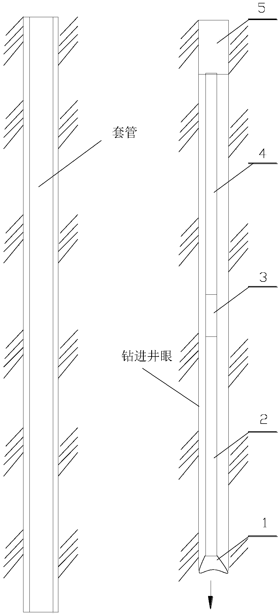
[0033] figure 1 As shown, the anti-collision drilling tool assembly for the vertical well section of dense cluster well group includes: drill bit 1, drill bit upper collar 2, strong magnetic nipple 3, centralizer lower collar 4, full-hole centralizer 5; drill bit 1, drill bit upper The drill collar 2, the strong magnetic short joint 3, the drill collar 4 at the lower part of the centralizer, and the full eye centralizer 5 are connected by threads in sequence. During the drilling process, the drill bit 4 is located at the bottom of the well and is used for rock-breaking drilling; the upper drill collar 2 of the drill bit, the strong magnetic short joint 3, the lower drill collar 4 of the centralizer, and the full-hole centralizer 5 are combined to form a combined structure for changing The drilling tendency of the drill bit; the centralizer 5 is connected with the drilling tool assembly on the upper part of the centralizer 5 .

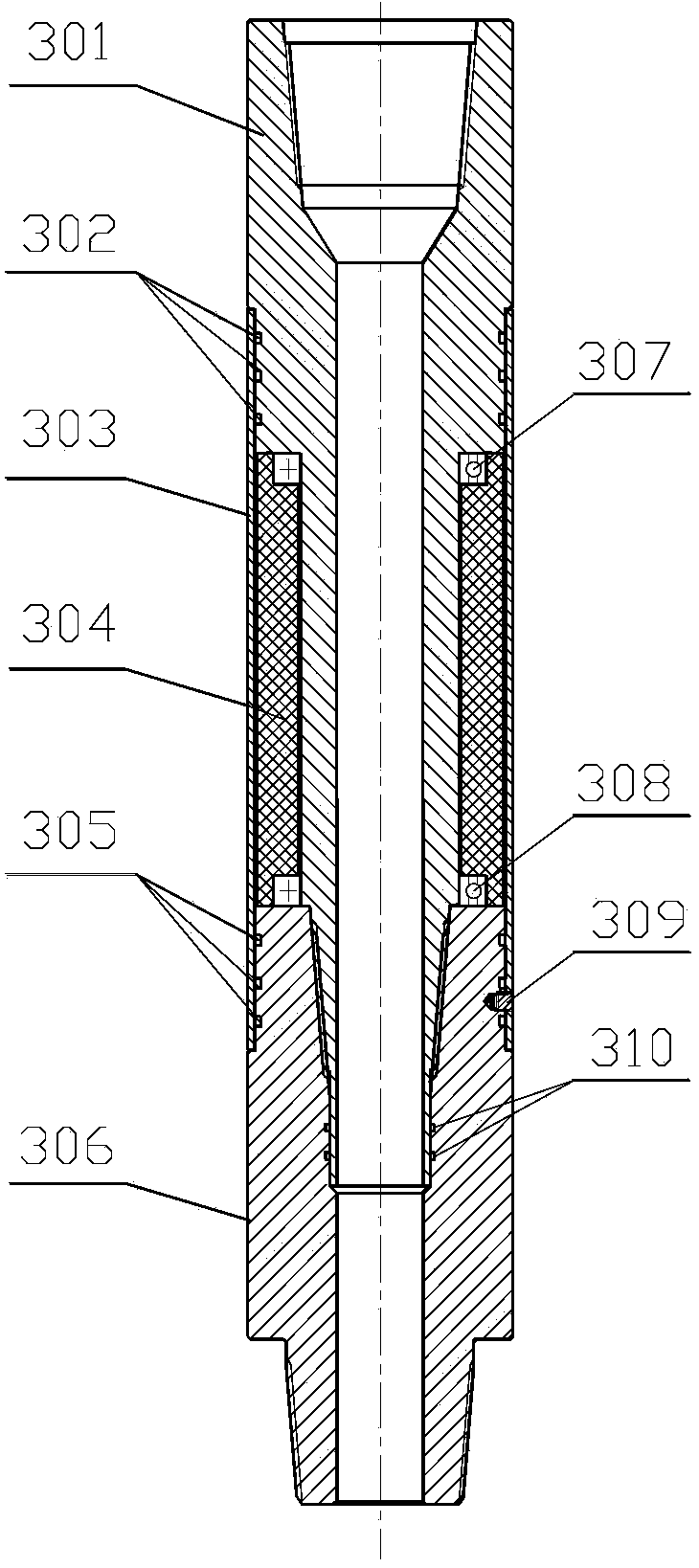
[0034] figure 2 As shown, the strong magnetic ...


PUM


Abstract

The inventionbelongs to the field of petroleum engineering and relates to an anti-collision drilling assembly for vertical sections in dense cluster well groups and an anti-collision method thereof. The anti-collision drilling assembly for vertical sections in dense cluster well groups comprises a drill bit, a drill bit upper collar, a strong magnet sub, a centralizer lower collar, a packed hole centralizer; the drill bit, the drill bit upper collar, the strong magnet sub, the centralizer lower collar, and the packed hole centralizer are sequentially connected in a threaded manner; the strong magnet sub comprises a strong magnet which is a cylinder having a through hole. The anti-collision drilling assembly for vertical sections in dense cluster well groups and the anti-collision method thereof have the advantages that a principle is simple, manually making anti-collision obstacle-bypassing measures or changing the original drilling method is not required, adding high-precision equipment is not required, construction of other wells is unaffected, the perfect function of automatic conversion from active anti-collision obstacle bypassing to normal drilling in the drilling process is achieved, no risks of other aspects are caused to drilling during the application process, special requirements for ground facilities, drilling strings and drill bit types are avoided, and the popularization and use is benefited.

Description

technical field [0001] The invention belongs to the field of petroleum engineering, and in particular relates to an anti-collision drilling tool assembly and an anti-collision method between boreholes in the oil and gas drilling process, in particular to an anti-collision drilling tool assembly and an anti-collision method for vertical sections of dense cluster well groups. touch method. Background technique [0002] At present, large cluster wells are often designed and drilled on land and offshore platforms to obtain underground oil and gas energy, thereby reducing the development cost of oil and gas resources and improving development efficiency. However, during the drilling process of this type of well, the problem of collision between wellbores becomes very prominent, and the problem of wellbore collision in vertical well sections is especially difficult to solve. [0003] The existing technologies and methods for anti-collision between boreholes have been disclosed in...

Claims


Application Information

Patent Timeline
Patent Type & Authority Applications(China)
IPC IPC(8): E21B17/04E21B7/04
Inventor 刘永旺管志川
Owner CHINA UNIV OF PETROLEUM (EAST CHINA)
Learn More