Axial flow type mine ventilator

A ventilator, axial flow technology, applied in mine/tunnel ventilation, mining equipment, mechanical equipment, etc., can solve the problems of high energy consumption, poor ventilation effect, complex structure, etc., and achieve low energy consumption and easy handling operation, small size effect

Inactive Publication Date: 2014-06-04
WUXI WASHING MACHINERY FACTORY
View PDF0 Cites 1 Cited by
  • Summary
  • Abstract
  • Description
  • Claims
  • Application Information

AI Technical Summary

Problems solved by technology

The traditional mine ventilator equipment has complex structure, poor ventilation effect and high energy consumption

Method used


Image

  • Axial flow type mine ventilator
  • Axial flow type mine ventilator

Examples


Embodiment Construction

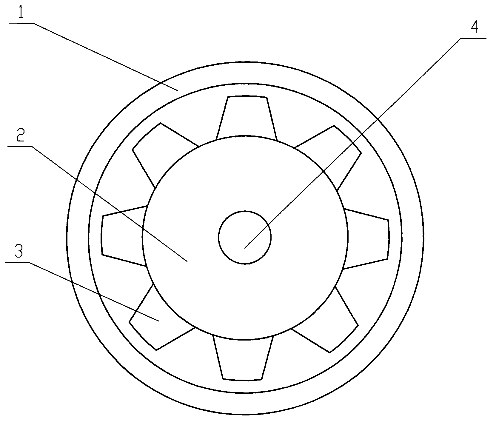
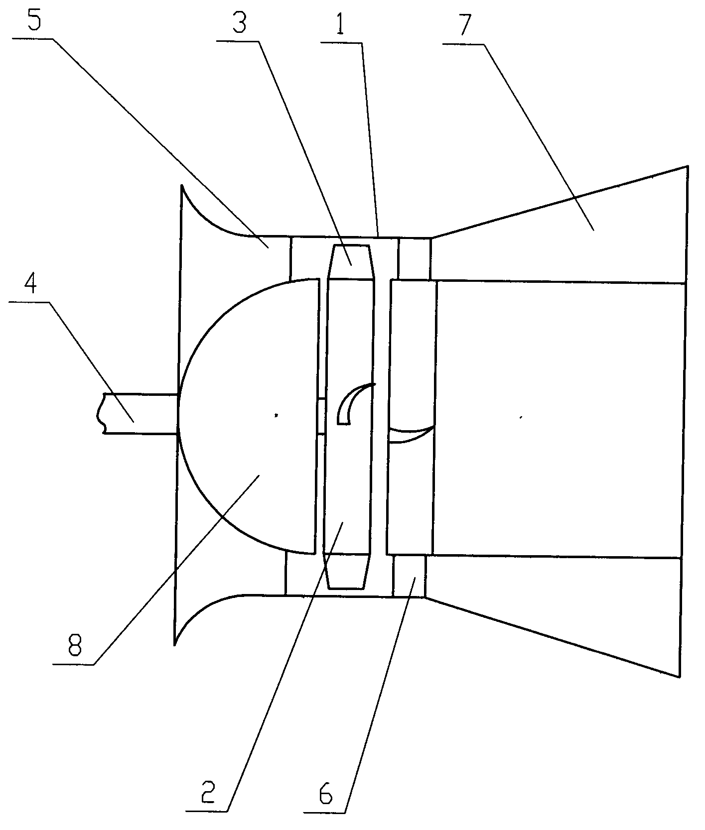
[0012] The specific embodiments of the present invention will be further described below in conjunction with the accompanying drawings.

[0013] See figure 1 , figure 2 , the present invention comprises a crankshaft 4, a casing 1, an air collector 5 and an air diffuser 7 connected to the casing 1, the crankshaft 4 is fixedly connected to a hub 2, a streamlined body 8 and a rectifier 6, and the periphery of the hub 2 has a wheel The leaves 3 and the streamline body 8 are placed at the junction of the casing 1 and the air collector 5, the rectifier 6 is placed at the junction of the casing 1 and the air diffuser 7, and the hub 2 is placed in the casing 1 and located at the streamline body 8 and rectifier 6. The streamline body 8 is hemispherical, and the air collector 5 is conical, both of which contribute to the entry of air, and the rectifier 6 and the conical air diffuser 7 both contribute to the outflow of air.

[0014] The invention has the advantages of simple structur...


PUM


Abstract

The invention relates to an axial flow type mine ventilator. The axial flow type mine ventilator is characterized by comprising a crankshaft, a housing, an air inlet pipe and an air outlet pipe; the air inlet pipe and the air outlet pipe are connected with the housing, the crankshaft is fixedly connected with an impeller which is arranged in the housing, and the crankshaft is fixedly connected with a front guide device which is arranged at an orifice of the air inlet pipe. Compared with traditional mine ventilator equipment, the axial flow type mine ventilator has the advantages of being simple in structure, good in ventilation effect, low in energy consumption, small in size and convenient to carry and operate.

Description

Technical field: [0001] The invention relates to the field of mining equipment, in particular to mine ventilator equipment. Background technique: [0002] Under the coal mine, due to the impact of gas gushing, coal dust flying, personnel breathing, and decay of pit logs, harmful and toxic gases continue to increase; at the same time, as the depth of the well increases, the underground temperature also rises. Therefore, underground staff working in this environment for a long time will not only affect their health, but even suffocate them. Especially when the content of methane and coal dust in the air exceeds the specified value, it may cause a gas and coal dust explosion with serious consequences. In order to ensure the health and safe production of underground workers, it is necessary to continuously communicate the dirty air in underground roadways and working faces with the fresh air on the ground, and use centrifugal mine ventilators to improve working conditions. How...

Claims


Application Information

Patent Timeline
Patent Type & Authority Applications(China)
IPC IPC(8): F04D29/52E21F1/00
Inventor 丁建明
Owner WUXI WASHING MACHINERY FACTORY
Why Eureka
Try Eureka