
Lighting bulb

A light bulb and housing technology, applied in the field of lighting bulbs, can solve the problems of complex overall manufacturing process, light leakage, poor visual effect, etc. Effect

Inactive Publication Date: 2014-06-04
DONGGUAN MASSTOP LIQUID CRYSTAL DISPLAY +1
View PDF5 Cites 0 Cited by
  • Summary
  • Abstract
  • Description
  • Claims
  • Application Information

AI Technical Summary

Problems solved by technology

However, due to the limitation of the light-emitting angle (about 120°) of the light-emitting diode, the light-emitting diode bulb usually only has a lighting angle of about 120°, which is much smaller than the lighting angle of an incandescent bulb (about 300°), so it will have an illuminating angle of about 120°. Diode bulbs pose many limitations in lighting applications
In addition, although there has been a design that directly arranges the LED on the bulb housing to increase the lighting angle of the LED bulb, the light reflected by the light-transmitting bulb housing back to the LED will also be easily used from the bulb housing. The notch where the light-emitting diode is installed is emitted, resulting in problems such as low light use efficiency and light leakage.
[0003] In the prior art, although there has been a design in which LEDs are directly arranged on the bulb housing to increase the lighting angle of the LED bulb, this design will also bring about the overall complexity of the LED bulb manufacturing process and poor visual effects. Good and other disadvantages

Method used


Image

  • Lighting bulb
  • Lighting bulb
  • Lighting bulb

Examples


Embodiment Construction

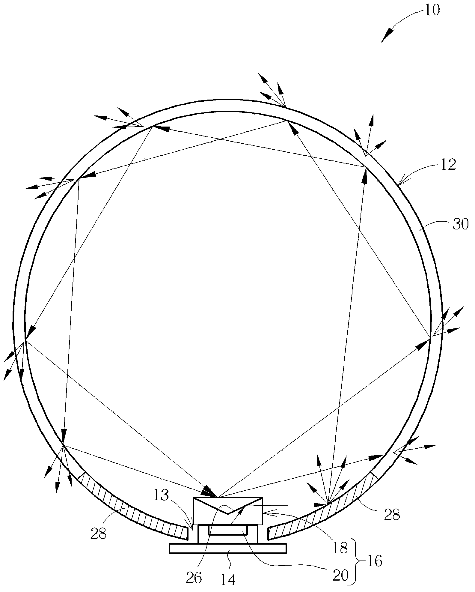
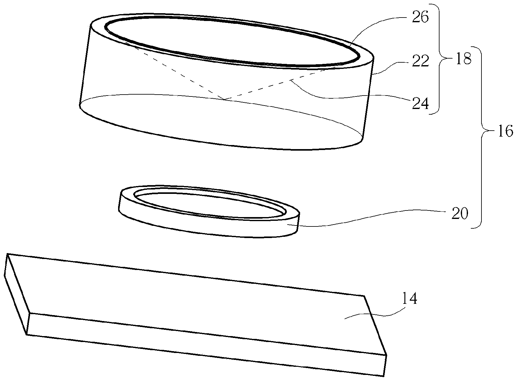
[0030] Please refer to figure 1 , figure 1 It is an internal schematic diagram of a lighting bulb 10 according to a first embodiment of the present invention. like figure 1 As shown, the lighting bulb 10 includes a light-transmitting bulb housing 12 , a circuit board 14 , and a lateral light-emitting device 16 . The light-transmitting bulb housing 12 has an opening 13 , and the circuit board 14 is correspondingly covered on the opening 13 to accommodate the lateral light-emitting device 16 together with the light-transmitting bulb housing 12 , wherein the light-transmitting bulb housing 12 can reflect It is composed of reflective materials with a rate greater than 90% and absorptivity less than 1%. The reflectivity here can be simply defined by the following formula.

[0031] Reflectance = 1- (absorptivity + transmittance)

[0032] In short, when light is incident on an object, the light will reflect, penetrate and absorb. Under the premise that the amount of incident ligh...


PUM


Abstract

The invention discloses a lighting bulb which comprises a light-transmitting bulb shell body, a circuit board and a side-direction light-emitting device. The light-transmitting bulb shell body is provided with an opening, the opening is covered with the circuit board, the side-direction light-emitting device comprises a light guide column structure and an upper light-emitting type light-emitting diode, an inclined reflection layer is formed in the light guide column structure, the upper light-emitting type light-emitting diode is arranged on the circuit board and below the light guide column structure, and light emitted by the upper light-emitting type light-emitting diode enters in the light guide column structure in an incident mode, is reflected by the inclined reflection layer, and enters in the light-transmitting bulb shell body in a lateral incident mode mode. Therefore, the lighting bulb enables light to enter in the bottom side edge area which is arranged on the light-transmitting bulb shell body in an incident mode and cannot be easily irradiated by the light, the problems that due to the fact that in the prior art, light can be emitted out of a gap of the bulb shell body, light use efficiency is low, and the light is leaked, and therefore the lighting angle and the light use efficiency of the lighting bulb can be effectively improved.

Description

technical field [0001] The present invention relates to a lighting bulb, in particular to a lighting bulb that uses a side-lighting device to emit light laterally to a light-transmitting bulb housing. Background technique [0002] Generally, traditional lighting bulbs are incandescent bulbs that emit light by heating tungsten filaments. However, in recent years, in order to meet the needs of environmental protection and energy saving, light-emitting diodes (LEDs) are used as light sources to replace tungsten filaments. However, due to the limitation of the light-emitting angle of the light-emitting diode (about 120°), the light-emitting diode bulb usually only has an illumination angle of about 120°, which is much smaller than the illumination angle of the incandescent bulb (about 300°). Diode bulbs pose a number of limitations in lighting applications. In addition, although there have been designs in which the light-emitting diodes are directly arranged on the light bulb h...

Claims


Application Information

Patent Timeline
Patent Type & Authority Applications(China)
IPC IPC(8): F21S2/00F21V8/00F21V7/00F21Y101/02F21K9/232F21Y115/10
Inventor 方崇仰
Owner DONGGUAN MASSTOP LIQUID CRYSTAL DISPLAY
Learn More