Active infrared dot-matrix type artificial road sign, intelligent body locating system and intelligent body locating method

An active infrared and dot-matrix technology, applied in general control systems, control/regulation systems, non-electric variable control, etc., can solve the problem of not using the location information of trail marking points, reducing the utilization rate of infrared points, and increasing the difficulty of production, etc. problem, to achieve the effect of reducing the difficulty of production, increasing the number of landmark points, and low cost

Active Publication Date: 2014-06-04
BEIJING INSTITUTE OF TECHNOLOGYGY
View PDF3 Cites 17 Cited by
  • Summary
  • Abstract
  • Description
  • Claims
  • Application Information

AI Technical Summary

Problems solved by technology

However, neither of the two patents records how to deal with two artificial road signs in the field of vision.
Moreover, there are large road markings and small road markings in an artificial road marking, making it more difficult and less accurate
In artificial landmarks, only large landmarks are used for three-dimensional positioning, and the position information of small landmarks is not utilized, which reduces the utilization rate of infrared points in landmarks

Method used


Image

  • Active infrared dot-matrix type artificial road sign, intelligent body locating system and intelligent body locating method
  • Active infrared dot-matrix type artificial road sign, intelligent body locating system and intelligent body locating method
  • Active infrared dot-matrix type artificial road sign, intelligent body locating system and intelligent body locating method

Examples


Embodiment Construction

[0032] The embodiments of the present invention will be further described in detail below in conjunction with the accompanying drawings.

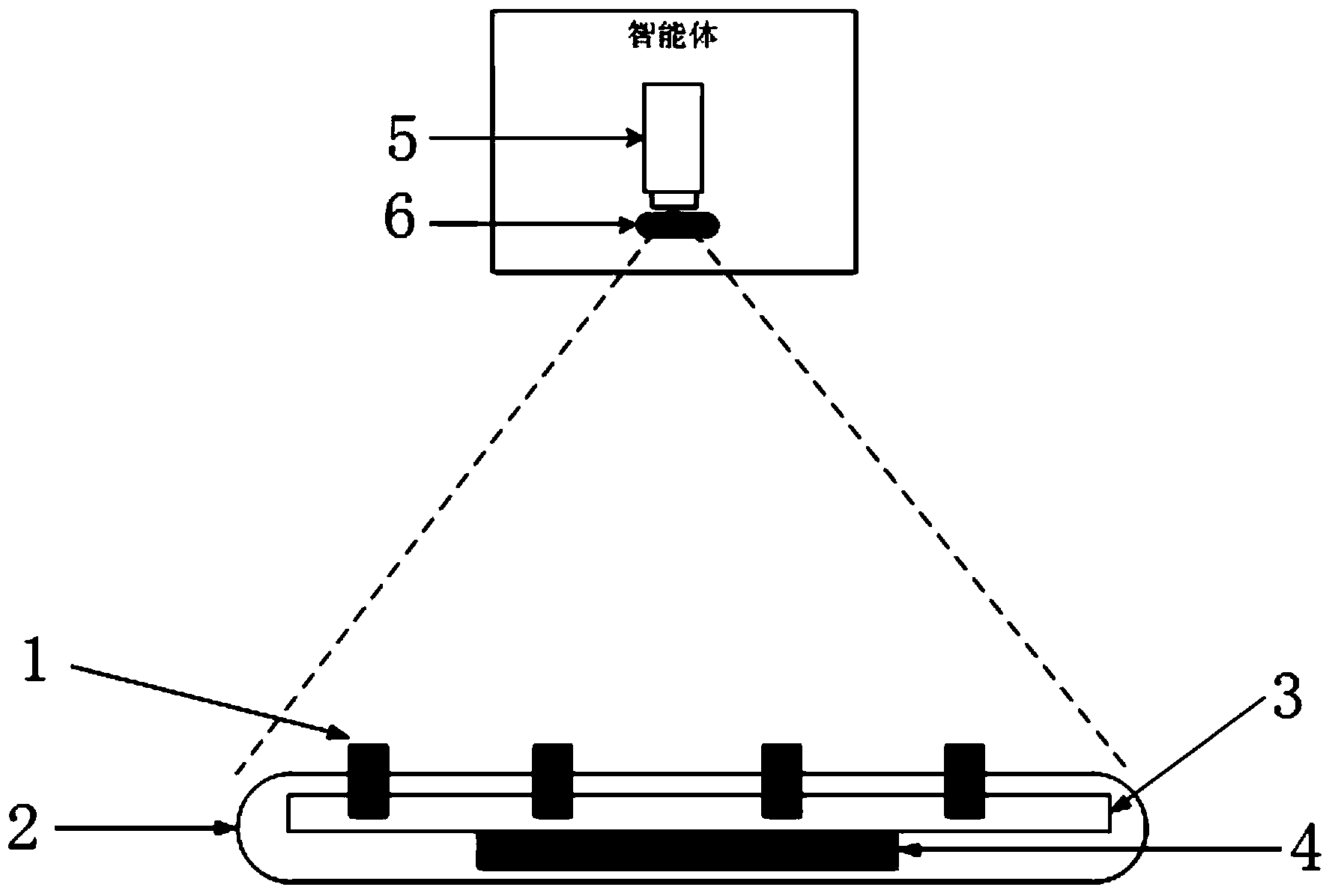
[0033]This embodiment provides an active infrared dot-matrix artificial road sign and an intelligent body positioning system and method based on the artificial road sign. It uses infrared LED lights of the same size to make artificial road signs, integrates identification ID coding and positioning, and reduces the cost of artificial road signs. It is difficult to make, improves the utilization efficiency of each LED light in the artificial road sign, and can handle the situation that there are multiple artificial road signs in the field of vision; when using it, an ordinary camera is used instead of an expensive infrared camera, which reduces the cost of the system.

[0034] The structure of the active infrared dot matrix artificial road sign is as follows: figure 1 As shown, it includes an array of infrared LED lamps, a planar circuit boar...


PUM


Abstract

The invention provides an active infrared dot-matrix type artificial road sign, an intelligent body locating system and an intelligent body locating method. According to each artificial road sign, an LED lamp array is made by adopting infrared LED (Light Emitting Diode) lamps with the same size, and a working state is identified by adopting a two-dimensional two-value matrix with rotation asymmetry and uniqueness. In the intelligent body locating system formed by the artificial road sign and the intelligent body locating method, the artificial road sign is sensed by adopting a camera provided with an infrared narrow band filter; then image coordinates of a center point of each infrared lamp are extracted from a shot image; through clustering of a minimum and nearest neighbor manner, a plurality of artificial road signs in a field of view are distinguished; array dots are coded by using an across linker method after each artificial road sign dot matrix is rotatably compensated, and codes of the artificial road signs are matched; world coordinates of the artificial road sign LED lamps are found according to the codes; and finally, three-dimensional pose position of a camera relative to the artificial road signs are solved by combining with image coordinates of the LED lamps and the world coordinates, and thus three-dimensional location or pose measurement of an intelligent body is realized.

Description

technical field [0001] The invention relates to an artificial road sign and intelligent body positioning system and method, in particular to an active infrared dot matrix artificial road mark and intelligent body positioning system and method, belonging to the field of three-dimensional measurement and positioning of intelligent bodies. Background technique [0002] Intelligent bodies such as robots and unmanned vehicles need to know their own position and posture in the environment. Using a vision system for 3D measurement has the advantages of low cost and precise positioning. At present, in the method of intelligent body positioning, the method of using natural landmarks or artificial landmarks for positioning has achieved many beneficial effects. Natural road signs do not require human intervention, have minimal changes to the environment, and have a high degree of intelligence. However, due to the lack of obvious characteristics of natural road signs in the environment...

Claims


Application Information

Patent Timeline
IPC IPC(8): G01C21/00
CPCG05B2219/37555G05B2219/40564G05D1/0234G06T7/70
Inventor 黄强陈晓鹏孟非张伟民周明亮黄高李敬
Owner BEIJING INSTITUTE OF TECHNOLOGYGY
Why Eureka
Try Eureka