
LED support and LED

A technology of LED brackets and LED chips, which is applied in the direction of electrical components, circuits, semiconductor devices, etc., can solve the problems of small size, low light transmittance, dark LED, etc., achieve good heat dissipation effect, large light-emitting area and angle, and extend LED The effect of longevity

Inactive Publication Date: 2014-06-04
梁建忠
View PDF10 Cites 4 Cited by
  • Summary
  • Abstract
  • Description
  • Claims
  • Application Information

AI Technical Summary

Problems solved by technology

[0002] The LED bracket is used to package the LED chip unit. This LED bracket is mainly for the chip unit with a power below 0.5W. At least 20 lamp beads need to be packaged in a single row. The chip emits light, which is used to reflect the light emitted by the chip. , with the passage of time, the light transmittance will gradually decrease, making the LED darker and darker; and the chip will generate a lot of heat at the same time, and now the LED bracket products tend to be smaller and smaller, in this case Under the traditional LED bracket, heat dissipation aluminum sheets or fans are installed on the bracket body to dissipate the heat energy generated by the chip unit to the surrounding air; and in order to be able to install more lamp beads and heat dissipation aluminum sheets or fans , it is bound to make the structure design of the LED bracket larger

Method used


Image

  • LED support and LED
  • LED support and LED
  • LED support and LED

Examples


Embodiment Construction

[0020] The following will clearly and completely describe the technical solutions in the embodiments of the present invention with reference to the accompanying drawings in the embodiments of the present invention. Obviously, the described embodiments are only some, not all, embodiments of the present invention. Based on the embodiments of the present invention, all other embodiments obtained by persons of ordinary skill in the art without making creative efforts belong to the protection scope of the present invention.

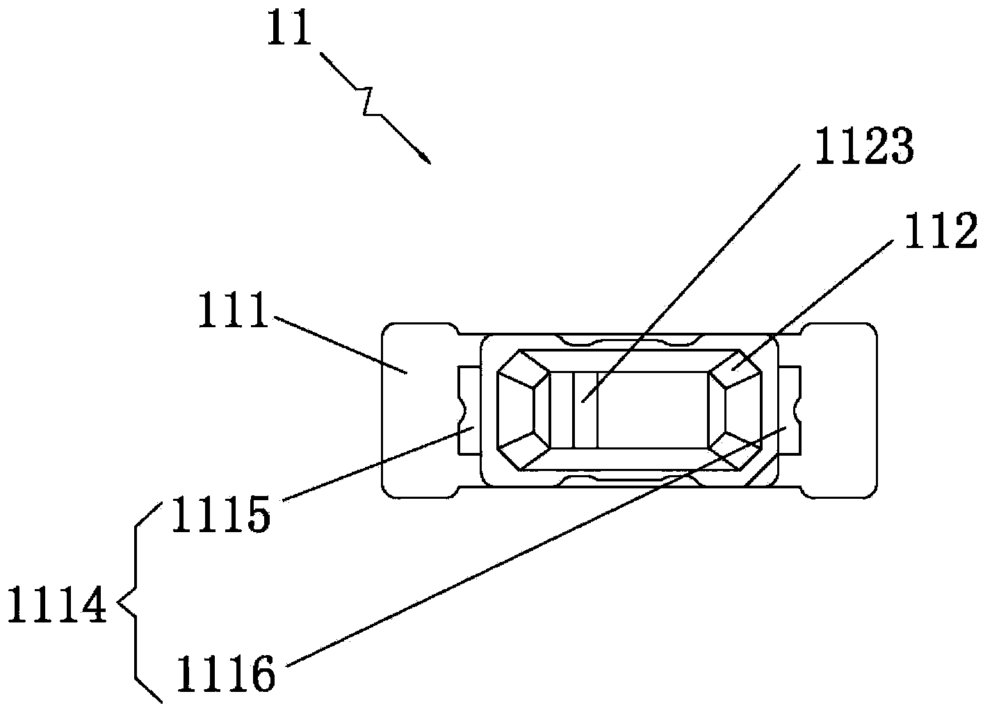
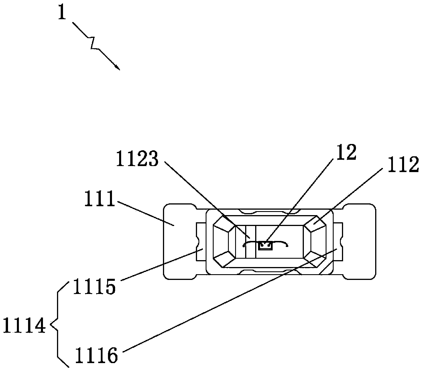
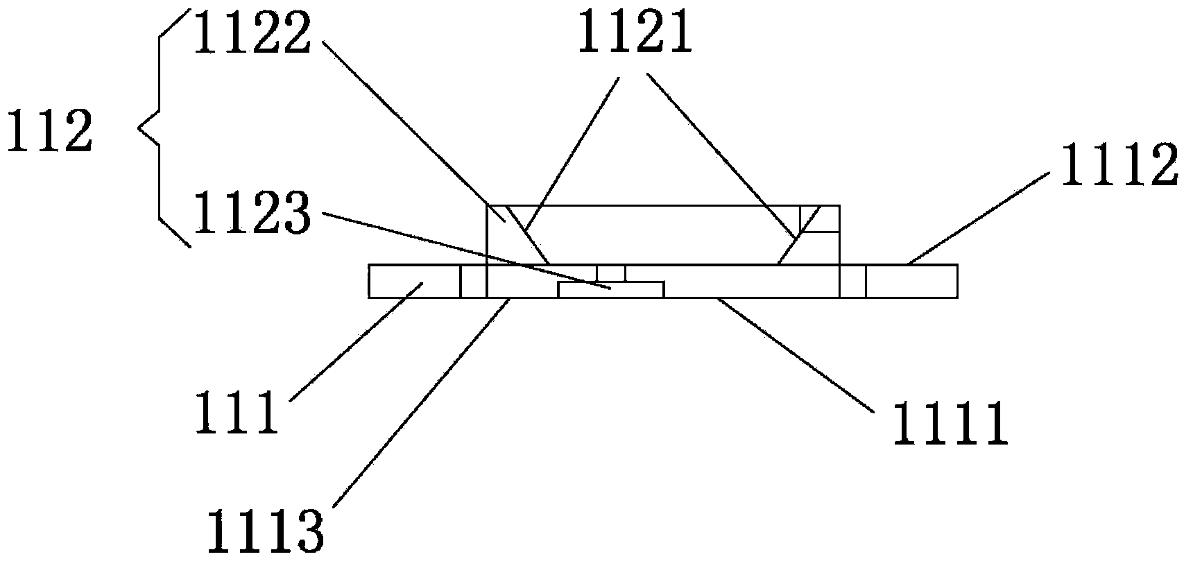
[0021] Such as Figure 1-Figure 4 , the embodiment of the present invention provides an LED bracket 11, which is applied to the packaging of the chip unit 12. The LED bracket 11 is used to conduct electricity and support the chip unit 12. The chip unit 12 is specifically described as a chip with a power of 0.5W. , the LED bracket 11 includes a base material 111 and a base 112 injection molded through a mold, the base material 111 is used for conducting electri...


PUM


Abstract

The invention provides an LED support and an LED. The LED support comprises a substrate and a base which is moulded through a die. The substrate and the base are molded into one piece. A chip unit is packaged on the substrate and is arranged inside the base. The inner wall of the base is provided with a reflection surface for reflecting light rays emitted from the chip unit. The reflection surface is moulded through a die. The substrate is provided with a heat dissipation layer for dissipating the heat from the chip unit. By smoothing and polishing the die for base moulding, the inner wall of the base is allowed to reach a smooth mirror surface effect, so that the light rays emitted from the chip unit can be reflected favorably, the light transmittance of the light rays emitted from the chip unit can be kept for a long time, and the advantages of large light-emitting area and angle are achieved; adding heat-dissipation aluminum sheets or fans to the substrate is avoided, and heat is dissipated through a heat dissipation layer in a thermal transmission manner; the heat dissipation effect is good; the service life of the LED is prolonged; the cost of the heat-dissipation aluminum sheets or the fans is saved on the premise of saving space utilization rate; and a simplification effect is achieved.

Description

technical field [0001] The invention relates to LED technology, in particular to an LED bracket and an LED. Background technique [0002] The LED bracket is used to package the LED chip unit. This LED bracket is mainly for the chip unit with a power below 0.5W. At least 20 lamp beads need to be packaged in a single row. The chip emits light, which is used to reflect the light emitted by the chip. , with the passage of time, the light transmittance will gradually decrease, making the LED darker and darker; and the chip will generate a lot of heat at the same time, and now the LED bracket products tend to be smaller and smaller, in this case Under the traditional LED bracket, heat dissipation aluminum sheets or fans are installed on the bracket body to dissipate the heat energy generated by the chip unit to the surrounding air; and in order to be able to install more lamp beads and heat dissipation aluminum sheets or fans , will inevitably make the design of the LED bracket s...

Claims


Application Information

Patent Timeline
Patent Type & Authority Applications(China)
IPC IPC(8): H01L33/48H01L33/60H01L33/64
CPCH01L33/486H01L33/60H01L33/641
Inventor 梁建忠
Owner 梁建忠
Learn More