Moving magnet type linear oscillation motor without inner stator

A technology of oscillating motors and inner stators, which is applied in the direction of electrical components and electromechanical devices, can solve the problems of complex structural iron core lamination, difficulty in stacking inner stators, and large volume of the whole machine, achieving compact structure, low cost, small size effect

Inactive Publication Date: 2014-06-04
ZHEJIANG SCI-TECH UNIV
View PDF7 Cites 2 Cited by
  • Summary
  • Abstract
  • Description
  • Claims
  • Application Information

AI Technical Summary

Problems solved by technology

[0005] The patent application number 200880001914 discloses a linear motor for a linear compressor, including an inner stator, an outer stator, and a mover composed of a plurality of permanent magnets. The inner stator is insulated from each other by stacking iron core blocks in the circumferential direction To be formed, the outer stator is formed by arranging core blocks at predetermined intervals in a circumferential direction and winding a coil around the core blocks, the permanent magnet is disposed between the inner stator and the outer stator with a predetermined gap, and Interacting and reciprocating along a straight line, its structure and iron core laminations are complex and difficult to maintain
[0006] The traditional moving magnet linear oscillation motor requires the inner stator to form a closed magnetic circuit, and the inner stator is radially distributed on the circumference, so there are disadvantages such as difficult stacking of the inner stator, difficult processing, high processing cost, and large volume of the whole machine.

Method used


Image

  • Moving magnet type linear oscillation motor without inner stator
  • Moving magnet type linear oscillation motor without inner stator
  • Moving magnet type linear oscillation motor without inner stator

Examples


Embodiment 1

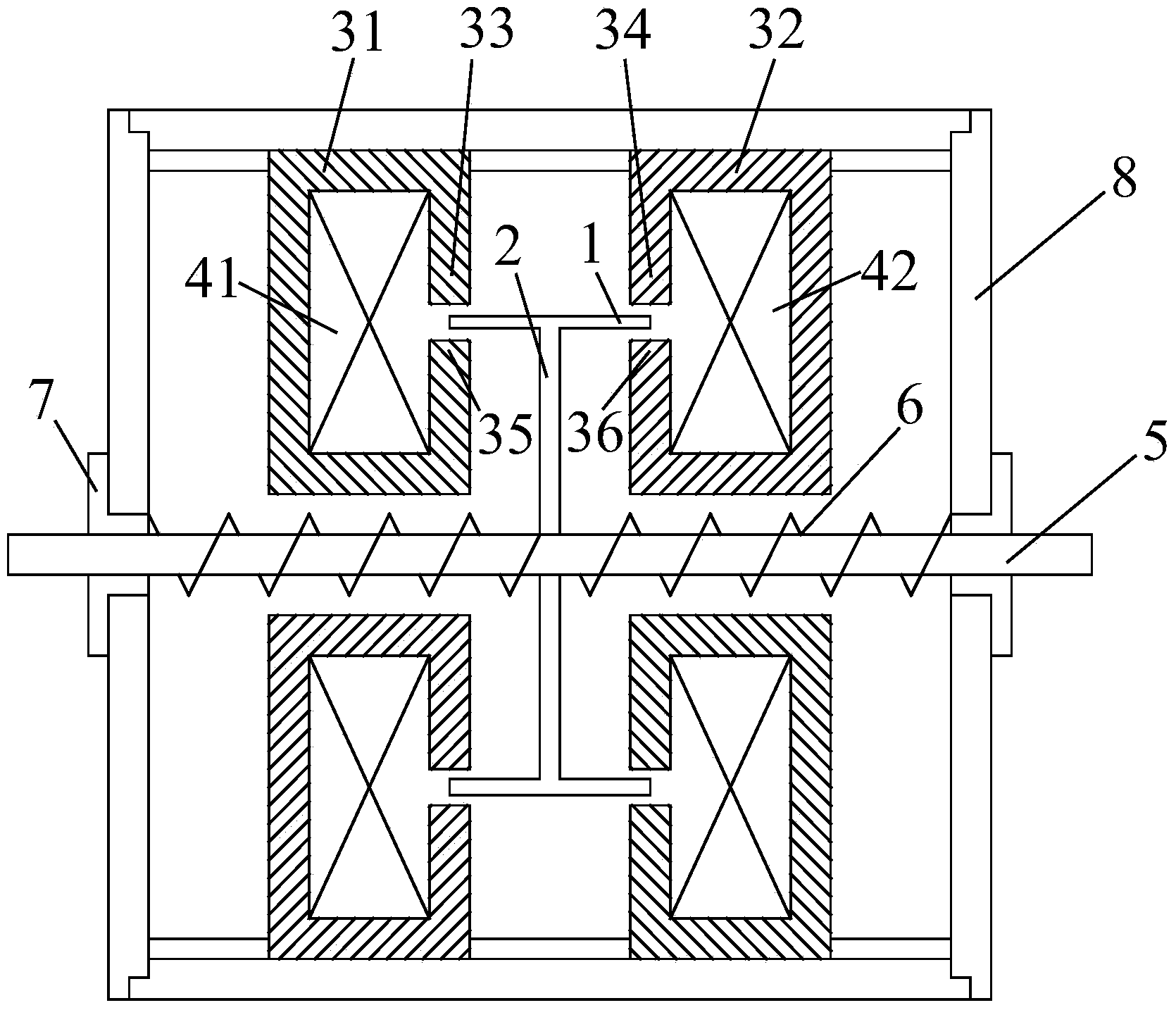
[0028] Embodiment 1, Figure 1 to Figure 7 Provided is a moving magnet type linear oscillation motor without inner stator; it includes a casing 8 in which a stator and a mover are arranged.

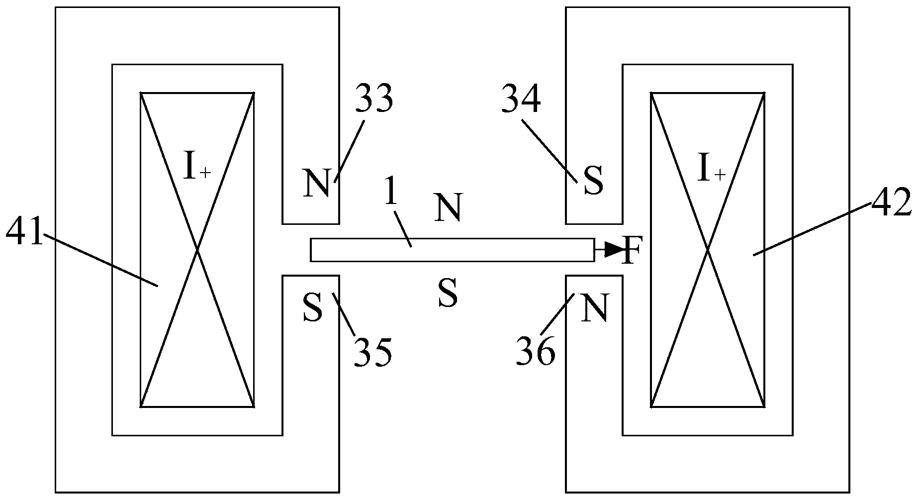
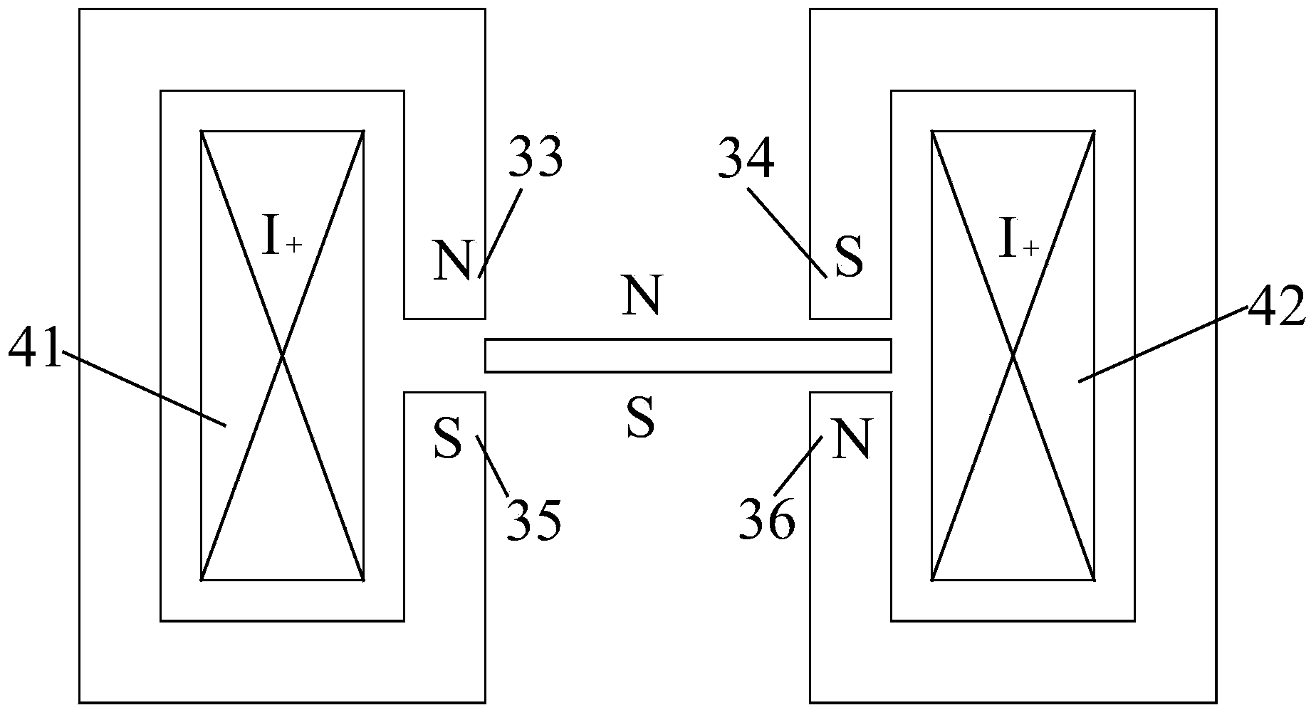
[0029] The stator is composed of a stator core, an armature winding and an annular winding support; the stator core is divided into a left stator core 31 and a right stator core 32 which are arranged symmetrically; the left stator core 31 and the right stator core The cores 32 are all "C" type stator cores, and the gap of the left stator core 31 is facing the gap of the right stator core 32; A number of small stator core blocks are assembled; the left armature winding 41 is arranged on the left annular winding support; the right stator core 32 is made of a hard plastic processed right annular winding The core blocks are assembled; the right armature winding 42 is set on the right annular winding support (the left armature winding 41 and the right armature winding 42 are arranged in oppos...


PUM


Abstract

The invention discloses a moving magnet type linear oscillation motor without an inner stator. The moving magnet type linear oscillation motor without the inner stator comprises stator cores and a permanent magnet arranged inside the machine shell, wherein the stator cores are C type cores, the upper tooth part and the lower tooth part of each C type stator core form an N pole and an S pole respectively after an armature winding is arranged, the permanent magnet is arranged between the two stator cores, tooth parts of the two stator cores right face each other, the N pole and the S pole of the two stator cores are opposite, the two poles of the permanent magnet right face the upper tooth parts of the two stator cores and the lower tooth parts of the two stator cores respectively.

Description

technical field [0001] The invention belongs to the field of linear motors, in particular to a linear oscillating motor with permanent magnets. Background technique [0002] The traditional technology uses transmission mechanisms such as cranks and leadscrews to convert the rotary motion of the rotary motor into linear reciprocating motion, which has problems such as complex structure, low efficiency, and poor mechanical reliability. Using a linear oscillating motor to realize linear reciprocating motion can save the transmission mechanism, reduce friction loss, and improve system efficiency and reliability. [0003] Linear oscillating motors include moving magnet linear oscillating motors, moving coil linear oscillating motors and moving iron linear oscillating motors. Among them, the moving magnet linear oscillating motor is a linear oscillating motor in which the permanent magnet material is used as the mover. The constant magnetic field generated by the permanent magnet...

Claims


Application Information

Patent Timeline
Patent Type & Authority Applications(China)
IPC IPC(8): H02K33/18H02K33/04
Inventor 雷美珍戴文战夏永明王立强腾伟峰
Owner ZHEJIANG SCI-TECH UNIV
Why Eureka
Try Eureka