Visible light communication method and system
A visible light communication and optical signal technology, applied in the field of visible light communication methods and systems, can solve the problems of reduced brightness, limited modulation bandwidth, signal distortion, etc., and achieve the effects of alleviating the reduction in information rate, maintaining high-speed communication, and reducing illumination.
- Summary
- Abstract
- Description
- Claims
- Application Information
AI Technical Summary
Problems solved by technology
Method used
Image
Examples
Embodiment 1
[0038] The visible light communication method in this embodiment includes the steps of adjusting the illuminance:
[0039] The step of adjusting the illuminance is a step in which the transmitting end adjusts the signal period and keeps the signal pulse width constant, so that the illuminance of the transmitted light signal is not greater than a preset value. This method is usually used for the light brightness of the sending end that needs to be felt by the human eye to be very small, so as to achieve the effect of turning off the light, so the illuminance of the optical signal at the sending end needs to be less than or equal to the preset illuminance.
[0040] The sending end usually includes an LED light source. On the one hand, the LED light source can play the role of lighting, and at the same time, it is responsible for sending a signal to the receiving end through its unnoticeable on and off. When LED lighting is not needed (that is, the LED that needs to be reduced il...
Embodiment 2
[0043] In the visible light communication method of this embodiment, the sending end of the visible light signal includes the step of adjusting the illumination;
[0044] The illuminance adjustment step: adjusting the signal cycle and keeping the signal pulse width constant, so that the illuminance of the transmitted light signal is not greater than a preset value;
[0045] After the illuminance adjustment step, the sending end calculates the duty cycle of the light signal and expresses it in the form of a power, the duty cycle is greater than or equal to 2 -n and less than 2 -(n+1) Between, use L-PPM modulation to generate the transmitted optical signal, where L=2 n , n is a positive integer, so that when the illuminance of the transmitted visible light decreases, the information transmission rate of the system will not decrease rapidly.
[0046] PPM: Plus Position Modulation pulse position modulation, when the signal period T PWM extended for pulse width T PWM(ON) 4 time...
Embodiment 3
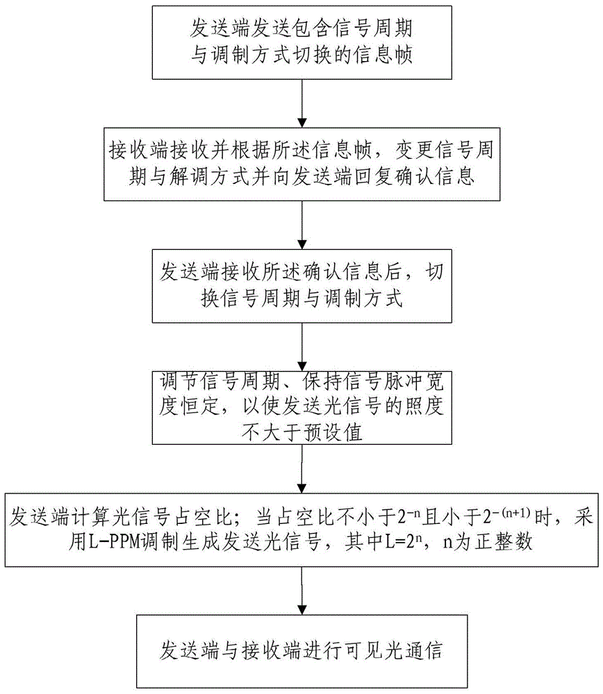
[0049] Such as figure 2 As shown, the visible light communication method of this embodiment includes the following steps in sequence:
[0050] Step S1: Before switching the signal period and modulation mode, the sending end sends an information frame including switching of the signal period and modulation mode;
[0051] Step S2: The receiving end receives and changes the signal period and demodulation mode according to the information frame, and replies confirmation information to the sending end;
[0052] Step S3: After receiving the confirmation information, the sending end switches the signal period and modulation mode. When a sending end needs to communicate with several receiving ends, the sending end communicates with each receiving end through time-division multiplexing, and the switching is completed in sequence.
[0053] Step S4: Adjusting the signal cycle and keeping the signal pulse width constant to ensure that when the illuminance of the transmitted optical sig...
PUM
 Abstract
Description
Claims
Application Information
 - R&D
- Intellectual Property
- Life Sciences
- Materials
- Tech Scout
- Unparalleled Data Quality
- Higher Quality Content
- 60% Fewer Hallucinations
Browse by: Latest US Patents, China's latest patents, Technical Efficacy Thesaurus, Application Domain, Technology Topic, Popular Technical Reports.
© 2025 PatSnap. All rights reserved.Legal|Privacy policy|Modern Slavery Act Transparency Statement|Sitemap|About US| Contact US: help@patsnap.com


