Turning device for output shaft of parallel-axis gearbox

An output shaft and gear box technology, applied in assembly machines, metal processing, metal processing equipment, etc., can solve problems such as affecting assembly accuracy, damage to the tip of gear teeth, ground damage, etc., and achieve the effect of convenient work.

Inactive Publication Date: 2014-06-11
南京恒誉名翔科技有限公司
View PDF0 Cites 3 Cited by
  • Summary
  • Abstract
  • Description
  • Claims
  • Application Information

AI Technical Summary

Problems solved by technology

[0002] When assembling the parallel shaft gearbox, after the output shaft and the output gear are pressed together, bearings and other accessories need to be installed on both sides of the output gear. The output shaft and the output gear must be turned 180°. In the actual assembly process, the Turning over manually on the ground will not only damage the ground but also easily damage the tooth tips of the gears, thus affecting the assembly accuracy

Method used


Image

  • Turning device for output shaft of parallel-axis gearbox

Examples


Embodiment Construction

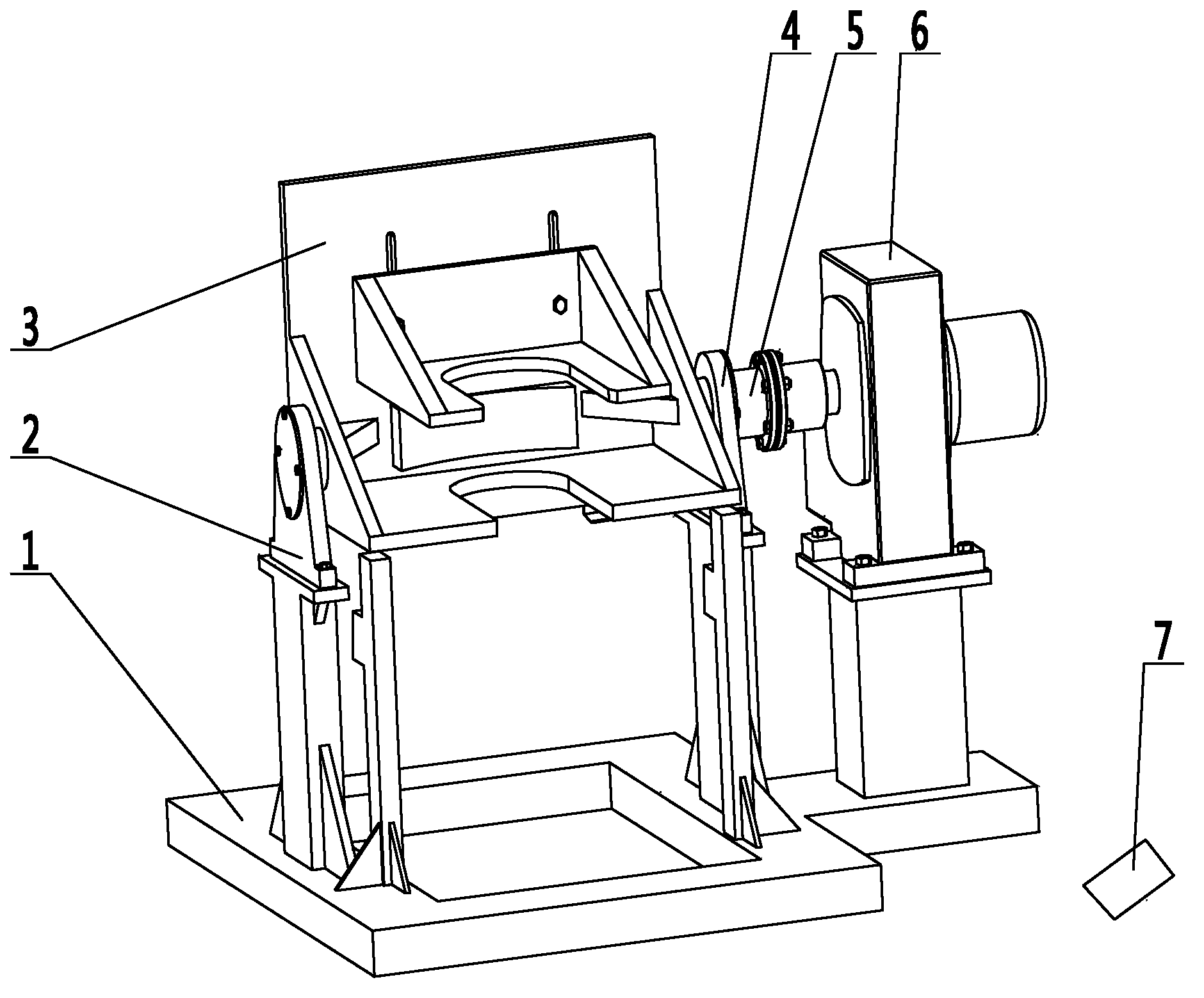
[0020] figure 1 Insert the left end bearing seat (2) and the right end bearing seat (4) respectively into the left and right end shaft heads of the turning frame (3), install the left end bearing seat (2) and the right end bearing seat (4) at the corresponding positions of the frame body (1) and fix them, remove the coupling (5) Install them on the shaft head at the right end of the overturn frame ⑶ and the output shaft of the reducer ⑹, place the reducer ⑹ on the corresponding position of the frame body ⑴, combine the coupling ⑸ and fasten the reducer ⑹ on the frame body (1) on. The worker puts the pressed output shaft and output gear on the overturn frame ⑶, steps on the forward foot switch ⑺, the output shaft of the reducer ⑹ drives the overturn frame ⑶ to rotate forward through the coupling ⑸, and stops automatically when it reaches the designated position After the assembly is completed, the worker steps on the reverse foot switch⑺, the output shaft of the reducer ⑹ driv...


PUM


Abstract

The invention discloses a turning device for an output shaft of a parallel-axis gearbox. The turning machine consists of a frame body, a left-end bearing block, a turning stand, a right-end bearing block, a coupling, a speed reducer and pedal switches and is characterized in that the left-end bearing block and the right-end bearing block respectively penetrate into a left-end shaft head and a right-end shaft head of the turning stand and are arranged at corresponding positions of the frame body and are fixed; the coupling is detached and is respectively arranged on the right-end shaft head of the turning stand and an output shaft of the speed reducer; the speed reducer is placed at the corresponding position of the frame body; the coupling is combined and then the speed reducer is fastened on the frame body. The output shaft and an output gear which are subjected to press mounting are placed on the turning stand by workers, the forward pedal switch is treaded and the output shaft of the speed reducer drives the turning stand to rotate forwards by the coupling and automatically stops when reaching the designated position; when the assembly is finished, the workers tread the backward pedal switch and the output shaft of the speed reducer drives the turning stand to rotate backwards by the coupling and automatically stops when reaching the designated position, and the output shaft and the output gear which are subjected to press mounting are moved away by the workers.

Description

technical field [0001] The invention is an overturning mechanism, specifically, an overturning mechanism applied to the assembly of parallel shaft gearboxes. Background technique [0002] When assembling the parallel shaft gearbox, after the output shaft and the output gear are pressed together, bearings and other accessories need to be installed on both sides of the output gear. The output shaft and the output gear must be turned 180°. In the actual assembly process, the Turning over manually on the ground will not only damage the ground but also easily cause damage to the tooth tips of the gears, thereby affecting the assembly accuracy. Contents of the invention [0003] The purpose of the present invention is to provide a turning mechanism that realizes semi-automation, simple structure, convenient operation and safety. [0004] The purpose of the present invention is achieved like this: [0005] It mainly includes frame body ⑴, left end bearing seat ⑵, overturn frame...

Claims


Application Information

Patent Timeline
Patent Type & Authority Applications(China)
IPC IPC(8): B23P21/00B23Q7/00
CPCB23P19/02
Inventor 李冰李忠喜李相武王瑛
Owner 南京恒誉名翔科技有限公司
Why Eureka
Try Eureka