Eureka AIR delivers breakthrough ideas for toughest innovation challenges, trusted by R&D personnel around the world.

Heater multi-pipe heat conducting type shell-tube water storage bearing heat interchanger and manufacturing technology thereof

A heat-conducting shell and heat-exchanger technology, which can be applied to heat-exchanger types, heat-exchanger shells, and indirect heat-exchangers, etc., can solve the problems of low effective utilization of heat, water leakage in the welds of connecting pipes, and small heat transfer area. , to achieve the effect of reducing oxidation corrosion, reducing stress deformation, and accelerating thermal conductivity

Active Publication Date: 2014-06-11
山东利能换热器有限公司
View PDF10 Cites 4 Cited by
  • Summary
  • Abstract
  • Description
  • Claims
  • Application Information

AI Technical Summary

Problems solved by technology

More importantly, the heat in the center of the heating tube is not easily absorbed by the cold fluid, so the heat transfer effect is poor
The above-mentioned prior art has the technical defects of small heat transfer area, low effective utilization rate of heat, poor heat transfer effect and water leakage from the welding seam of the connecting pipe.

Method used


Image

  • Heater multi-pipe heat conducting type shell-tube water storage bearing heat interchanger and manufacturing technology thereof
  • Heater multi-pipe heat conducting type shell-tube water storage bearing heat interchanger and manufacturing technology thereof
  • Heater multi-pipe heat conducting type shell-tube water storage bearing heat interchanger and manufacturing technology thereof

Examples


Embodiment Construction

[0042] The present invention will be further described below in conjunction with accompanying drawing and specific embodiment:

[0043] The present invention is a heating multi-tube heat conduction shell tube water storage pressurized heat exchanger such as Figure 1 to Figure 19 shown.

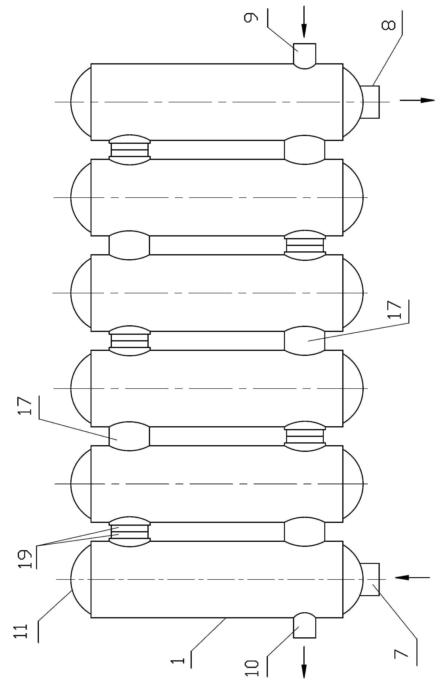
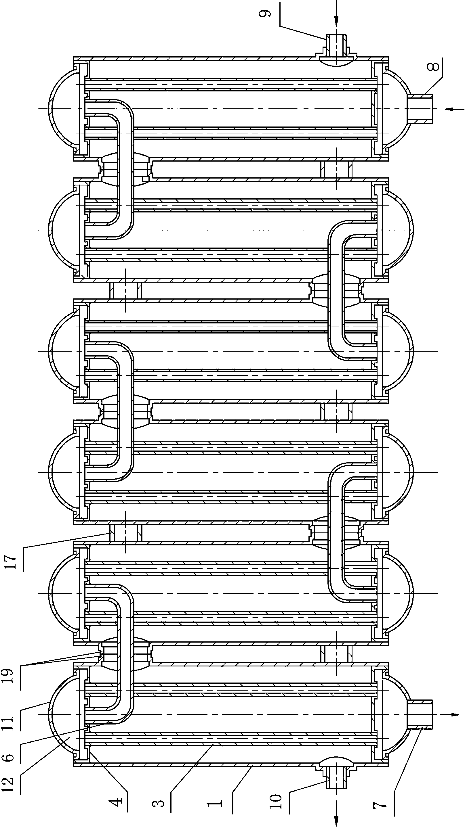
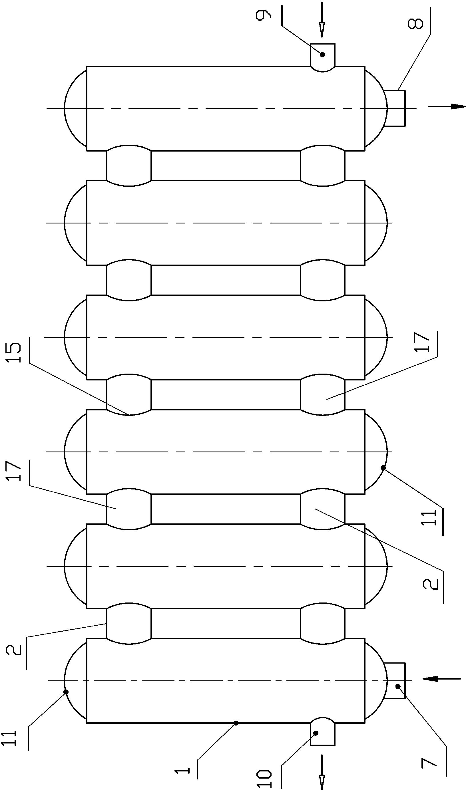
[0044] 1, the present invention as figure 1 , figure 2 , image 3 , Figure 4 , Figure 5 , Figure 6 As shown, it includes a plurality of cold water round pipes 1, cold water inlet pipe joints 9 and cold water outlet pipe joints 10, heating air inlet pipe joints 7 and heating air outlet pipe joints 8, and the two ends of the cold water round pipes 1 are respectively welded with end caps. Plate 11, one end of the plurality of cold water round pipes 1 and one end of the side pipe and the adjacent cold water round pipe 1 have a cold water pipe connection port 15 on the arc surface pipe wall between the adjacent cold water round pipes 1. Cavity; cold water pipe connection port 15 is prov...


PUM


Abstract

The invention provides a heater multi-pipe heat conducting type shell-tube water storage bearing heat interchanger and a manufacturing technology thereof. The heat interchanger comprises multiple round cold water pipes; head external blocking plates are welded at two ends of the round cold water pipes; heater pipe connecting blocking plates are welded in pipe openings at two ends of the round cold water pipes; round heater pipe connecting openings are formed on the heating pipe connecting blocking plates; pipe cavities are directly welded and communicated by the adjacent round cold water pipes through straight round cold water communicating pipes or butt-welded wall pulling pipes; at least one round heater pipe is penetrated into the cavity of each round cold water pipe; pipe openings of two ends of each round heater pipe are in welded connection with connecting openings of the round heater pipe on the heater pipe connecting blocking plates; round heater communicating pipes are in welded communication with the heater pipe connecting blocking plates or the round heater communicating pipes are sequentially welded and communicated with the head external blocking plates and are communicated with a thermal fluid shunting cavity to form a thermal fluid circulated heat transmission passage. The heat interchanging structure is more scientific and reasonable; the heat transmission area is improved by 55%-100%; the heat conduction rate is accelerated; the heat exchanging effect is excellent. The welding joints of the communicating pipes among the cavities are difficultly subjected to water leakage.

Description

technical field [0001] The invention relates to a heating heat exchanger which can be installed and used on a household heating pipe network for heating and exchanging hot water for bathing, and relates to a pressure-bearing multi-pipe heat conduction water storage heat exchanger with connected pipes; especially relates to a heating system A multi-tube heat-conducting shell-and-tube water storage pressurized heat exchanger and its manufacturing process. Background technique [0002] 1. The applicant applied for the patent No. 200720019175.2 on March 10, 2007, and the utility model name is "anti-scaling type counterflow heat exchanger". The authorized announcement number is CN20102875Y, and the authorized announcement date is: 2008.02. 13. [0003] 2. On September 11, 2011, the applicant applied for a patent with the patent number 201110267666.X and the invention name "Pipe Unicom Parallel Welded Pressure Heat Exchanger", and the date of its authorization announcement was Ja...

Claims


Application Information

Patent Timeline
Patent Type & Authority Applications(China)
IPC IPC(8): F28D7/10
CPCF28F9/26F28D7/16
Inventor 张伟张冲
Owner 山东利能换热器有限公司
Why Eureka
Eureka Blog
Learn More