
Arc-shaped curve boundary folding waveguide slow wave structure

A technology of folded waveguide and curved waveguide, which is applied in the field of microwave vacuum electronic devices, can solve the problems of difficulty in processing parts, increased process complexity, and low coupling impedance, and achieve the effect of improving gain and efficiency and improving coupling impedance

Active Publication Date: 2014-06-11
NO 12 RES INST OF CETC
View PDF4 Cites 26 Cited by
  • Summary
  • Abstract
  • Description
  • Claims
  • Application Information

AI Technical Summary

Problems solved by technology

[0006] The technical problem to be solved in the present invention is that, for the traditional folded waveguide slow wave structure with semicircular curved boundary, not only the coupling impedance is low, but also the difficulty of processing parts and the complexity of the process will increase with the increase of the application frequency. In order to overcome For these difficulties, it is necessary to develop a new type of folded waveguide slow-wave structure, which can obtain high coupling impedance of the slow-wave structure without increasing the difficulty and complexity of the process, and improve the short-wave structure with this type of slow-wave structure as the core. The performance of millimeter wave and terahertz vacuum electronic devices, the present invention proposes a curved curved boundary folded waveguide slow wave structure

Method used


Image

  • Arc-shaped curve boundary folding waveguide slow wave structure
  • Arc-shaped curve boundary folding waveguide slow wave structure
  • Arc-shaped curve boundary folding waveguide slow wave structure

Examples


Embodiment Construction

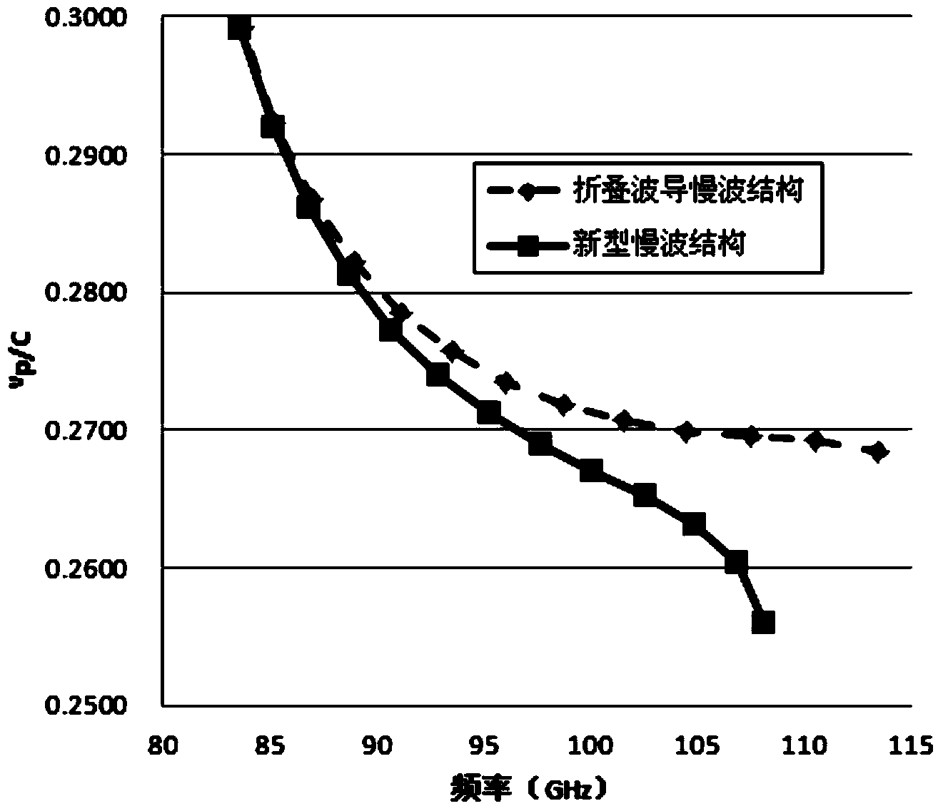
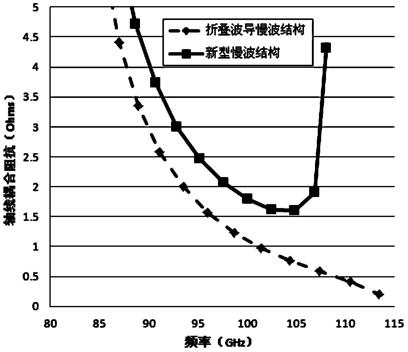
[0017] refer to figure 1 , figure 2 , represents the three-dimensional schematic diagram of the folded waveguide slow-wave structure and the schematic diagram of a single geometric period. In the figure, a represents the length of the broad side of the straight waveguide segment in the folded waveguide, b represents the length of the narrow side of the straight waveguide segment in the folded waveguide, and h represents the straight waveguide segment in the folded waveguide height, the geometric period is 2p, and the electron beam channel radius is r c , figure 2 The radius of the inner arc is r in , the radius of the outer arc is r out , the center point is O, and the line segment distance is Y in and Y out ,refer to Figure 5 with Image 6 The curve representing the simulated calculation, that is, the 3mm band in the intersection area of ​​the short millimeter wave band and the terahertz wave band, the structure size of the specific scheme of the curved curved bound...


PUM


Abstract

The invention relates to a microwave vacuum electronic device, in particular to an arc-shaped curve boundary folding waveguide slow wave structure, and belongs to the technical field of microwave vacuum electrons. The novel folding waveguide slow wave structure is a periodic structure of a series of straight waveguides and arc-shaped boundary curve waveguides, inner boundaries Cin and / or outer boundaries Cout of the curve waveguides are non-semicircles, and the positions (Yin and / or Yout) of arc circle centers (Oin and / or Oout) and radius sizes (Rin and / or Rout) are adjusted to increase the widths of the curve waveguides to strengthen electron beam direction electromagnetic fields of gaps of the straight waveguides. By means of the arc-shaped curve boundary folding waveguide slow wave structure, under the condition that the technology complexity and accuracy are not improved, the coupled impedance is improved, and the arc-shaped curve boundary folding waveguide slow wave structure is suitable for the improvement of gains and efficiency of short millimeter waves and terahertz devices.

Description

technical field [0001] The invention belongs to the field of microwave vacuum electronic devices, and in particular relates to an arc curved boundary folded waveguide slow wave structure. Background technique [0002] The slow wave structure is mainly used in traveling wave microwave vacuum electronic devices (it can also be used as a resonant cavity to expand the interaction standing wave device), and its role is to reduce the phase velocity of the electromagnetic wave transmitted in it, so that it can be synchronized with the electron beam, so as to Obtaining effective interaction between injected waves belongs to the core part of microwave vacuum electronic devices. [0003] As the frequency increases to the range of short millimeter wave (40GHz-300GHz) or even terahertz (300GHz-3000GHz), the most commonly used slow wave structure is greatly restricted in use due to technical problems such as processing and heat dissipation. Therefore, the new slow wave structure The exp...

Claims


Application Information

Patent Timeline
IPC IPC(8): H01J23/24
Inventor 蔡军冯进军邬显平
Owner NO 12 RES INST OF CETC
Learn More