
Novel surge protection device

A surge protector, a new type of technology, is applied in the direction of protection that responds to overcurrent, emergency protection circuit devices, and emergency protection circuit devices for limiting overcurrent/overvoltage. Protection of equipment, large installation space and other issues, to prolong the time of fire accidents, improve the effect of lightning protection, and reduce the effect of installation space

Active Publication Date: 2014-06-11
孙巍巍
View PDF9 Cites 16 Cited by
  • Summary
  • Abstract
  • Description
  • Claims
  • Application Information

AI Technical Summary

Problems solved by technology

However, when the power system fails, SPD overcurrent short circuit, power frequency current passes, its current value may not reach the starting value of the overcurrent protection device, the overcurrent protection device does not operate, resulting in continuous power frequency current passing, the lightning protection component Fever SPD catches fire
If the start-up value of the over-current protection device is selected to be small, although it can be started, it is difficult to resist the impact of lightning current, and the SPD cannot discharge the lightning current normally.
Therefore, the existing overcurrent protection device has a serious blind zone in the protection of SPD. In this area, the overcurrent protection device does not operate and cannot break the SPD fault path.
In addition, the existing overcurrent protection device is installed separately from the SPD, which requires a large installation space, and the wiring is complicated, which increases the residual voltage and threatens the protected equipment

Method used


Image

  • Novel surge protection device
  • Novel surge protection device
  • Novel surge protection device

Examples


Embodiment Construction

[0017] Below in conjunction with accompanying drawing and embodiment the present invention is further described:

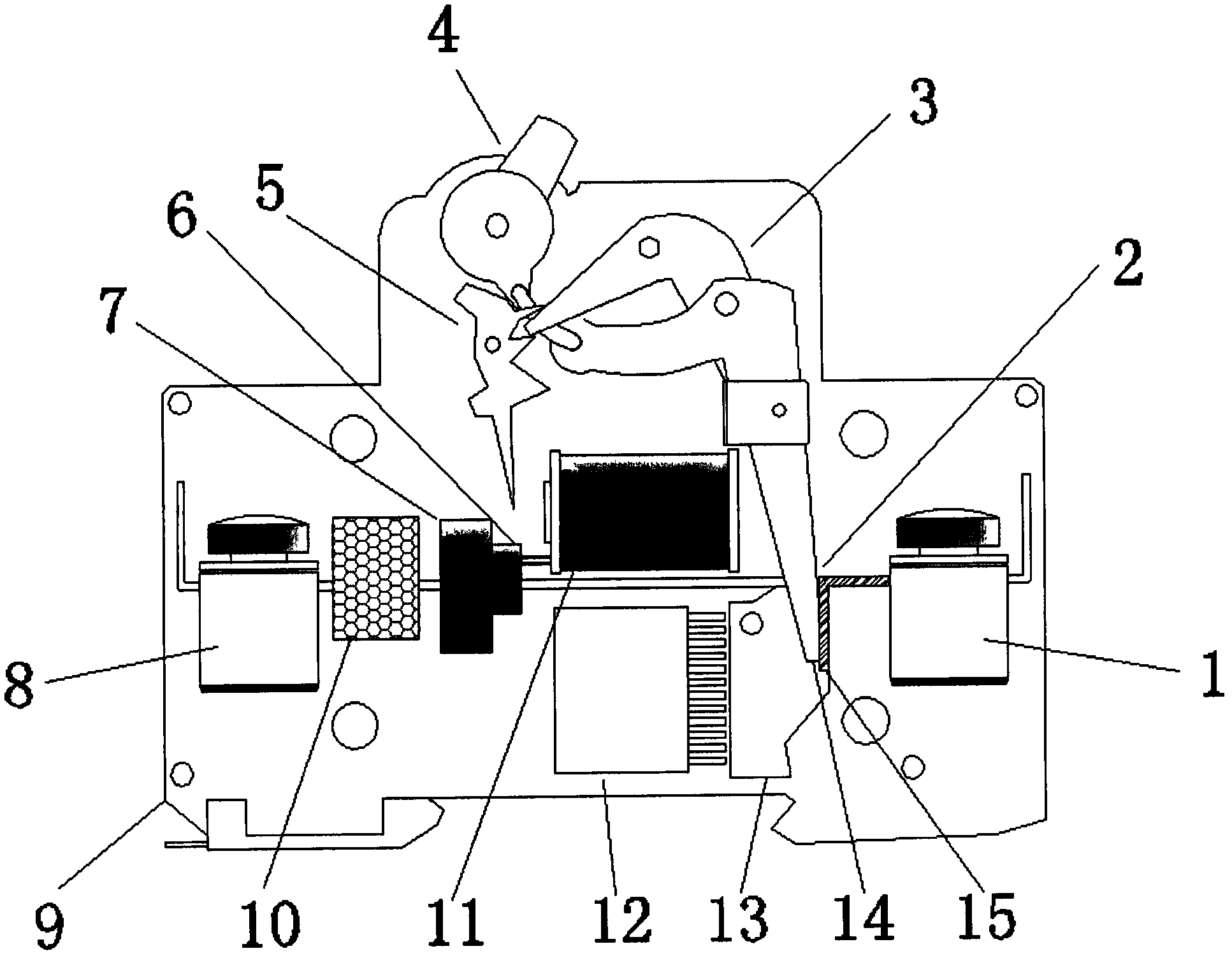
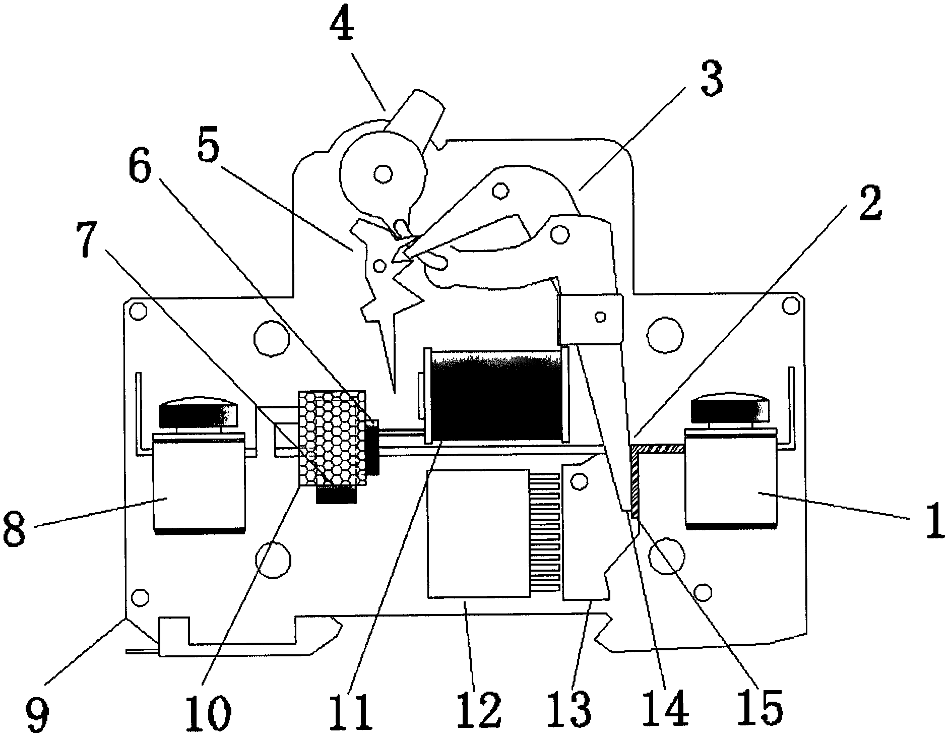
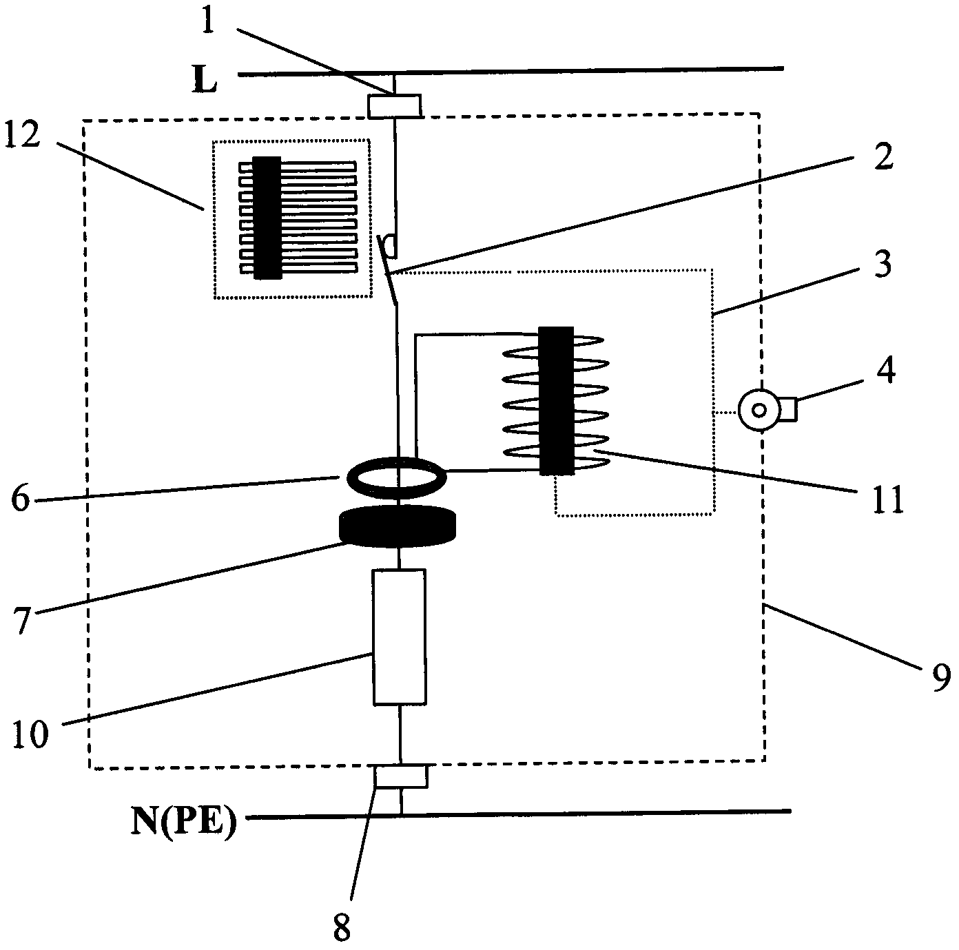
[0018] Such as figure 1 , 2 , 3, 1 is the upper terminal, 2 is the breaking contact, 3 is the trip mechanism, 4 is the closing wrench, 5 is the lock plate, 6 is the current sensor, 7 is the power frequency current suppressor, 8 is the The lower terminal, 9, shell, 10, lightning protection element, 11, delay stepping electromagnet, 12, arc extinguishing grid, 13, arc extinguishing magnetic blowing plate, 14, moving contact, 15, static contact.

[0019] figure 1 It is a structural schematic diagram of the first embodiment of the present invention, wherein the lightning protection element (10) is horizontally connected with the power frequency current suppressor (7).

[0020] figure 2 It is a structural schematic diagram of the second embodiment of the present invention, in which the lightning protection element (10) and the power frequency current suppressor (7...


PUM


Abstract

The invention relates to a novel surge protection device which mainly comprises breaking contacts (a fixed contact and a moving contact), a tripping mechanism, a stepping electromagnet, a switch-on wrench, a locking plate, a current sensor, a power frequency current suppressor, a delay stepping electromagnet, an arc chute, an arc extinction magnetic blow-out plate, an upper terminal, a lower terminal and a lightning protection element. The upper terminal is connected with the breaking contacts, the power frequency current suppressor, the lightning protection element and the lower terminal in series. The delay stepping electromagnet moves fast when power frequency currents pass through current signals output by the current sensor, the locking plate is pushed, the tripping mechanism is driven to turn off a whole surge protection device access. The delay stepping electromagnet does not move when lightning currents pass, and the lightning currents can be discharged smoothly. The novel surge protection device effectively solves the protection dead zone problem of an existing surge protection device backup protection device, lowers residual voltages, and is safe and reliable.

Description

technical field [0001] The invention belongs to the technical field of surge protection for electronic and electric equipment. Background technique [0002] Lightning is a special weather phenomenon caused by the discharge of charged clouds in the air. Lightning is an important cause of damage to electronic equipment, which threatens the safe and stable operation of electronic information systems in various fields such as construction, railways, civil aviation, communications, industrial control, and military. Installing a surge protective device (SPD) on metal lines such as power lines, signal lines, and control lines connected to electronic equipment is one of the important measures for lightning protection. Surge protectors have been widely used in various fields and play an important role in lightning protection. The quality of its state directly affects its lightning protection effect, thus bringing hidden dangers to the safety of the protected equipment. [0003] Th...

Claims


Application Information

Patent Timeline
IPC IPC(8): H02H9/02H02H3/08
Inventor 孙巍巍
Owner 孙巍巍
Learn More