Mobile terminal and charging control method of mobile terminal

A charging control method and mobile terminal technology, applied in the field of mobile terminals and their charging control, can solve problems such as shortening battery life and affecting charging quality, and achieve the effects of improving safety, prolonging service life, and protecting batteries

Active Publication Date: 2014-06-11
NUBIA TECHNOLOGY CO LTD
View PDF6 Cites 22 Cited by
  • Summary
  • Abstract
  • Description
  • Claims
  • Application Information

AI Technical Summary

Problems solved by technology

When the temperature of the charging process is too high, it will not only affect the quality of charging, but also easily shorten the life of the battery

Method used


Image

  • Mobile terminal and charging control method of mobile terminal
  • Mobile terminal and charging control method of mobile terminal
  • Mobile terminal and charging control method of mobile terminal

Examples


Embodiment 1

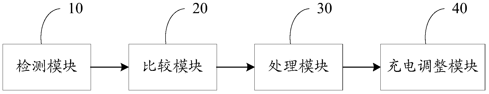
[0045] see figure 1 , which is a block diagram of a mobile terminal provided in the first embodiment of the present invention.

[0046] A mobile terminal, which includes: a detection module 10 , a comparison module 20 , a processing module 30 , and a charging adjustment module 40 .

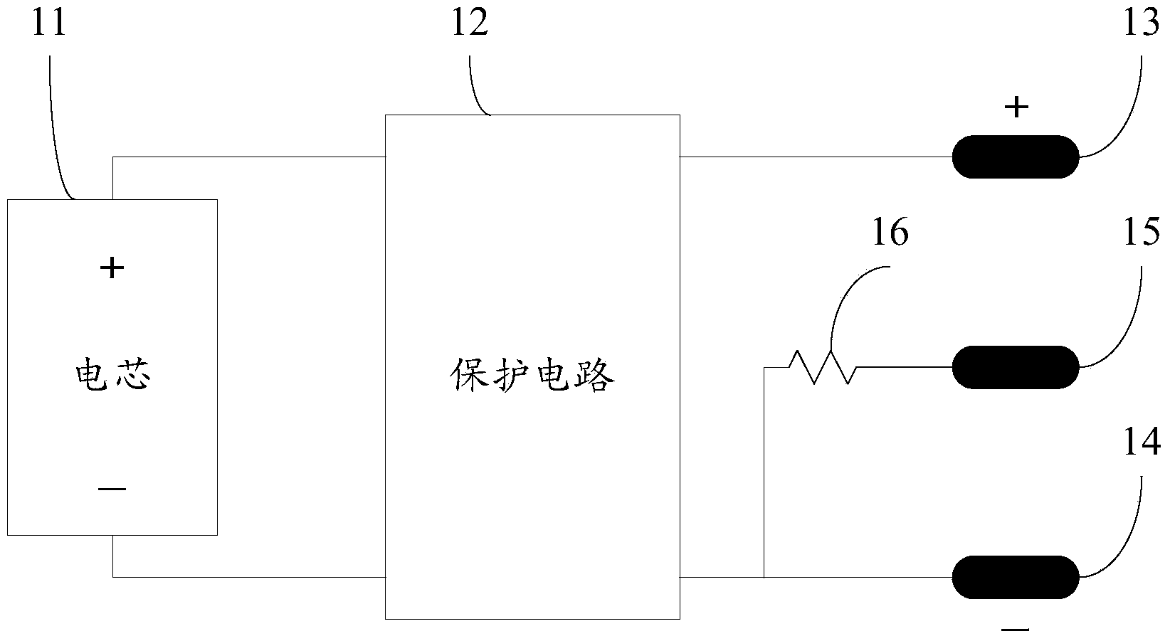
[0047] Wherein, the detection module 10 is used for detecting the temperature of the battery of the mobile terminal. The detection module 10 can be arranged around the battery of the mobile terminal, or attached to the battery of the mobile terminal. The detection module 10 may be a temperature detection circuit or a temperature sensor. In the first embodiment, the detection module 10 is taken as an example of a temperature detection circuit for illustration. The temperature detection circuit includes a thermistor, a voltage dividing resistor, a voltage reading unit, and a temperature conversion unit. see figure 2 , the battery of the mobile terminal includes a cell 11 , a protection circuit...

Embodiment 2

[0067] Compared with Example 1, the difference between the two lies in:

[0068] In the second embodiment, the detection module is a temperature sensor.

Embodiment 3

[0070] Compared with Example 1, the difference between the two lies in:

[0071] In the third embodiment, the detection module includes a temperature detection circuit and a temperature sensor. The detection module outputs the larger value of the temperature of the battery of the mobile terminal detected by both the temperature detection circuit and the temperature sensor to the comparison module.

[0072] Alternatively, in the third embodiment, the detection module includes a temperature detection circuit and a temperature sensor. The detection module outputs the temperature of the battery of the mobile terminal detected by both the temperature detection circuit and the temperature sensor to the comparison module.

[0073] The comparison module selects the larger value among the temperatures of the battery of the mobile terminal detected by both the temperature detection circuit and the temperature sensor, and compares it with the preset temperature.


PUM


Abstract

The invention provides a mobile terminal which comprises a detecting module, a comparison module, a processing module and a charging adjustment module. The detecting module is used for detecting the temperature of a battery of the mobile terminal, the comparison module is used for receiving the temperature, transmitted by the detecting module, of the battery and comparing the temperature of the battery with the preset temperature to obtain the relation, the processing module is used for determining charging adjustment parameters of the battery according to comparison results of the temperature of the battery with the preset temperature, and the charging adjustment module is used for adjusting a charging current of the battery according to the charging adjustment parameters. The invention further provides a charging control method of the mobile terminal. By means of the mobile terminal and the charging control method of the mobile terminal, the charging current can be reduced, the temperature of the surface of the battery can be accordingly lowered, the safety of the battery is improved, the battery can be efficiently protected, and the service life of the battery can be further prolonged.

Description

technical field [0001] The present invention relates to the technical field of mobile terminals, in particular to a mobile terminal and a charging control method thereof. Background technique [0002] With the development and popularization of smart terminal devices, more and more users choose to use mobile terminals such as mobile phones for work, office or life entertainment. Users not only value the functionality of their phones, but also their battery life. [0003] At present, the method of prolonging the power supply time of mobile phones is mainly realized by using rechargeable batteries. [0004] In the general charging process, temperature is a very important environmental parameter. When the temperature of the charging process is too high, it will not only affect the quality of charging, but also easily shorten the life of the battery. Contents of the invention [0005] In view of this, the technical problem to be solved by the present invention is to provide ...

Claims


Application Information

Patent Timeline
Patent Type & Authority Applications(China)
IPC IPC(8): H02J7/00
Inventor 袁敏
Owner NUBIA TECHNOLOGY CO LTD
Why Eureka
Try Eureka