Check patentability & draft patents in minutes with Patsnap Eureka AI!

Data synchronization method

A data synchronization and data technology, which is applied in the field of digital signal transmission, can solve the problems of long delay time and high RAM depth requirements, and achieve good synchronous delay effect

Inactive Publication Date: 2014-06-11
TIANJIN ZHONGXING SOFTWARE
View PDF0 Cites 3 Cited by
  • Summary
  • Abstract
  • Description
  • Claims
  • Application Information

AI Technical Summary

Problems solved by technology

[0005] The embodiment of the present invention provides a method and device for data synchronization to solve the problem of high requirements on the depth of RAM and long delay time in the existing data synchronization technology

Method used


Image

  • Data synchronization method
  • Data synchronization method
  • Data synchronization method

Examples


Embodiment Construction

[0022] The specific implementation manners of a data synchronization method and device provided in the embodiments of the present invention will be described below with reference to the drawings in the description.

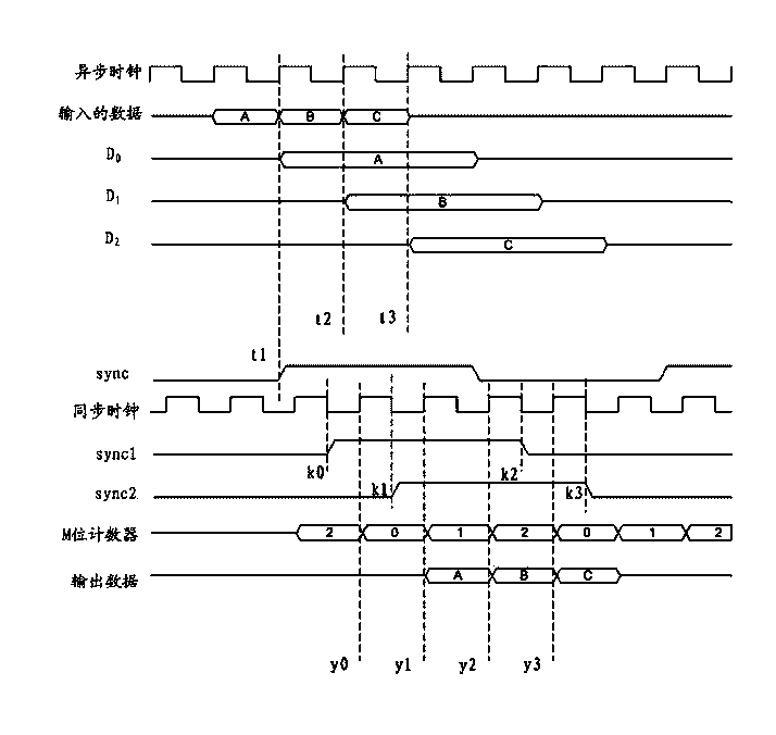
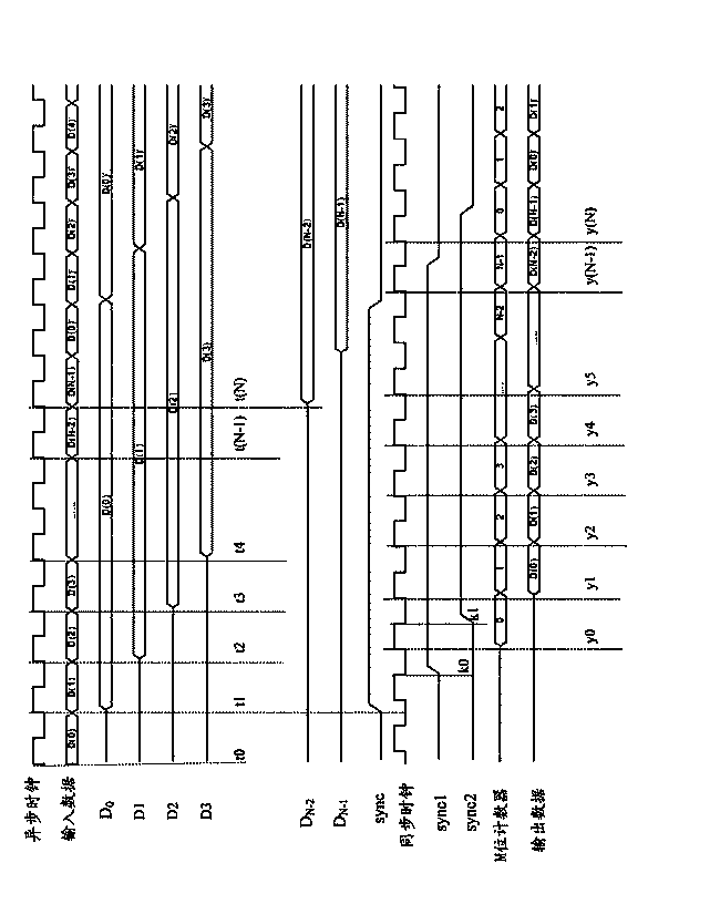
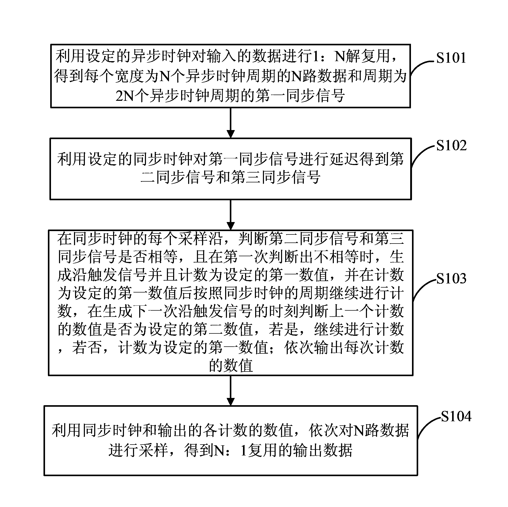
[0023] A data synchronization method provided by an embodiment of the present invention, such as figure 1 As shown, it specifically includes the following steps:

[0024] S101: Use the set asynchronous clock to perform 1:N demultiplexing of the input data to obtain N channels of data whose transmission rate is 1 / N of the input data and the first synchronous signal whose period is 2N asynchronous clock periods , where N is an integer greater than 1.

[0025] Preferably, the above-mentioned first synchronization signal can be obtained in the following manner:

[0026] The first synchronous signal is obtained by using the frame head position of any data path after demultiplexing as the rising edge or falling edge of the first synchronous signal, and taking at least...


PUM


Abstract

The embodiment of the invention provides a data synchronization method and device. The method includes the first step of carrying out one-to-N demultiplexing on input data through set asynchronous clocks to obtain N paths of data and first synchronizing signals, wherein the transmission rate of each path of data is one-Nth of the transmission rate of the input data, and the cycle of the first synchronizing signals is the cycle of 2N asynchronous clocks, the second step of carrying out delaying on the first synchronizing signals through set synchronous clocks to obtain second synchronizing signals and third synchronizing signals, the third step of judging whether the second synchronizing signals are equal to the third synchronizing signals at each sampling edge of the synchronous clocks, generating edge trigger signals and carrying out counting operation, and the fourth step of carrying out sampling on the N paths of data sequentially according to the synchronous clocks and output counting values to obtain N-to-one multiplex output data. The method solves the problems that requirements for RAM resources are high and the delay time is long.

Description

technical field [0001] The invention relates to the field of digital signal transmission, in particular to a data synchronization method and device. Background technique [0002] As digital systems grow larger and more complex, two or more clock domains are increasingly used in logic designs. In different clock domains, it is inevitable that data will be transferred to each other. Since there will be a certain phase difference and short-term frequency jitter between two different clocks, in order to ensure reliable data transmission, the impact of timing on functions must be fully considered when designing, otherwise it will be divided into two clock domains Data synchronization between failed. [0003] At present, the data conversion from the asynchronous clock domain to the synchronous clock domain is usually implemented by the method of caching data in the dual-port RAM: the asynchronous clock is used as the write clock of the dual-port RAM, and the write clock generate...

Claims


Application Information

Patent Timeline
IPC IPC(8): H04J3/06
Inventor 周恒箴
Owner TIANJIN ZHONGXING SOFTWARE
Features
  • R&D
  • Intellectual Property
  • Life Sciences
  • Materials
  • Tech Scout
  • Unparalleled Data Quality
  • Higher Quality Content
  • 60% Fewer Hallucinations
Learn More