Forced Circulation System and Its Constructed Forced Circulation Braking System

A circulating system and circulating pump technology, applied in the direction of brakes, brake components, brake transmission devices, etc., can solve problems such as brake failure, air resistance cannot be forced to be completely eliminated, and full-effect braking cannot be guaranteed at all times. Brake safety, eliminate brake slack, prevent brake failure and the effect of causing fire

Active Publication Date: 2017-01-25
厦门金利业科技有限公司
View PDF5 Cites 0 Cited by
  • Summary
  • Abstract
  • Description
  • Claims
  • Application Information

AI Technical Summary

Problems solved by technology

Therefore the brake fluid cannot circulate
[0009] 3) The air resistance cannot be completely eliminated by force
Brake calipers will generate heat when braking, lack of cooling measures and settings, high-intensity frequent braking will cause the temperature of the brake calipers to rise sharply, cause the brake fluid to vaporize, generate a large amount of air resistance, and cause brake weakness or failure , there are serious safety hazards and poor reliability factors
[0010] 4) Pollution booster pump
The brake oil pipe is connected to the middle of the brake caliper. Rust or impurities will be generated inside the brake caliper, which will generally gather in the middle and lower parts. When the brake fluid returns to the booster pump, pollution will occur, and serious pollution will cause brake failure.
[0011] 5) Full-effect braking; the air resistance inside the hydraulic system will be generated from time to time, but the method of manually releasing the air resistance cannot always discharge, and the full-effect braking cannot be guaranteed all the time, and there is a problem of low braking efficiency
[0012] 6) Braking and releasing the brakes are slow
In addition to low efficiency and poor flexibility, it will also cause many secondary problems such as heat generation of brake calipers.
[0013] 7) Lack of protection against impurities; the booster pump and the brake caliper are open and interactive, and are easily polluted by impurities, especially destructive impurities, and lack protection settings
[0014] No reports have been found on the forced circulation system and the forced circulation brake system it is built on

Method used


Image

  • Forced Circulation System and Its Constructed Forced Circulation Braking System
  • Forced Circulation System and Its Constructed Forced Circulation Braking System
  • Forced Circulation System and Its Constructed Forced Circulation Braking System

Examples


Embodiment 2

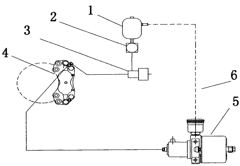
[0076] see image 3 , similar to Embodiment 1 of the forced circulation system of the present invention, the only difference is that the figure 2 The on-off valve 3 in is replaced by a one-way valve 301. Other tags and figure 2 correspond to the same.

Embodiment 3

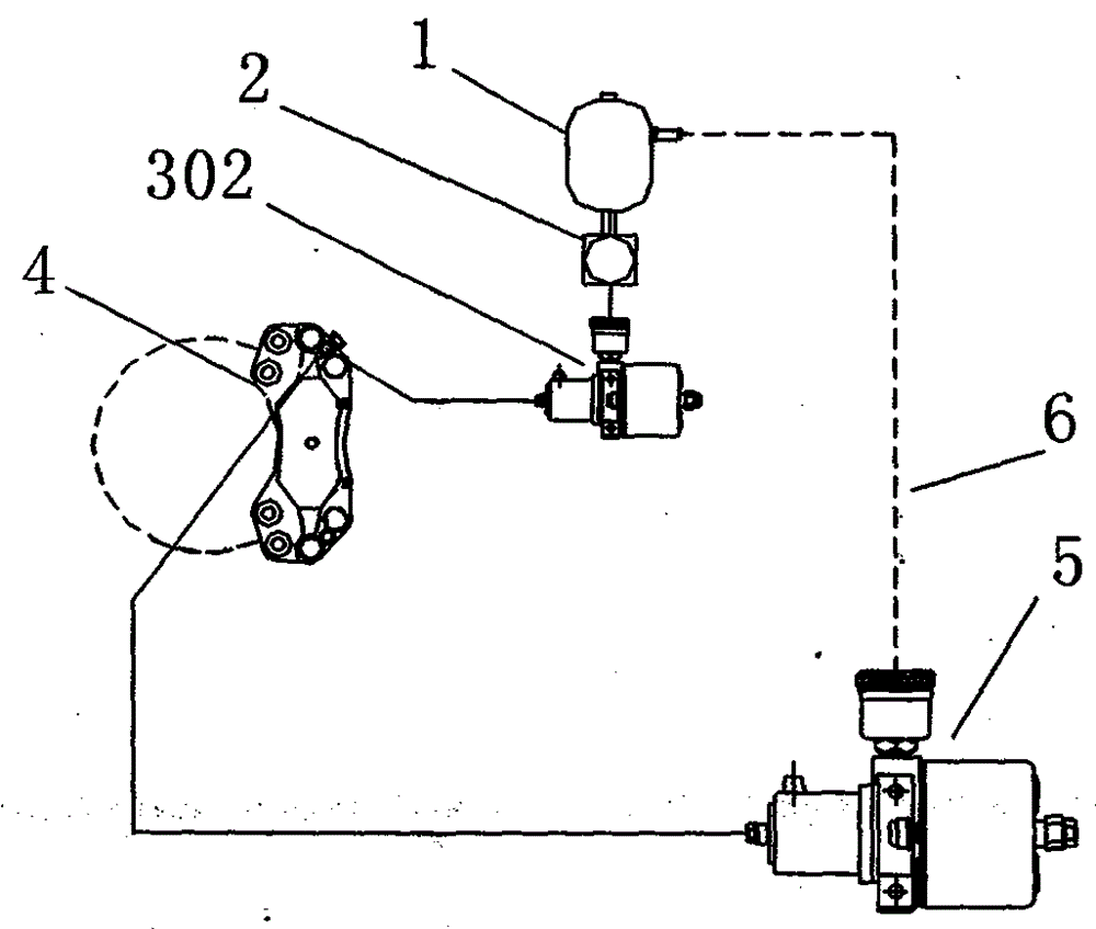
[0078] see Figure 4 , similar to Embodiment 1 of the forced circulation system of the present invention, the only difference is that the figure 2 The one-way valve 301 in is replaced by booster pump 302. Other tags and figure 2 correspond to the same.

[0079] Embodiment 1 of the forced circulation braking system of the present invention

[0080] This embodiment corresponds to the first technical solution of the forced circulation braking system of the present invention.

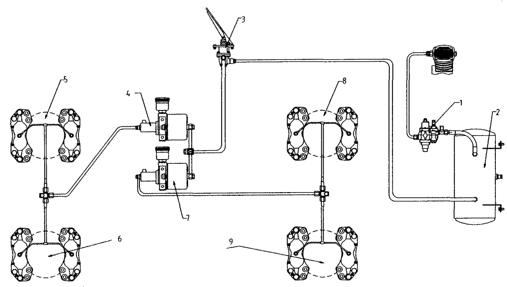
[0081] see Figure 5 , a forced circulation brake system, including a pressure regulating valve 21, a single-chamber air reservoir 20, a single-chamber air brake master valve 22, a front axle forced circulation system and a rear axle forced circulation system;

[0082] The front axle forced circulation system includes fuel tank 1, circulation pump 2, switch valve 3 (that is, switch control part), brake caliper group 4, afterburner pump 5, oil return pipe 6 (pipe marked with dotted line) and oil pipe....

Embodiment 7

[0105] This implementation corresponds to the third technical solution of the braking system of the forced circulation system in the present invention.

[0106] see Figure 8 , the forced circulation brake system described in this embodiment includes a pressure regulating valve 301, a double-chamber air storage tank 303, a double-chamber air brake master valve 312, a front axle forced circulation system and a rear axle forced circulation system;

[0107] The inlet of the pressure regulating valve 301 is connected to an external pressure gas source, the outlet of the pressure regulating valve 301 is connected to the inlet of the double-chamber air storage tank 303, and one outlet of the double-chamber air storage tank 303 is connected to one chamber of the double-chamber air brake master valve 312 through the air pipeline The air inlet, the other outlet of the double-chamber air storage tank 303 is connected to the air inlet of the other chamber of the double-chamber air brake ...


PUM


Abstract

The invention relates to a forced circulation system, which is applicable to vehicles, such as loaders and can realize full-effect braking through forced brake fluid circulation, and a forced-circulation brake system constructed therefrom. The forced circulation system comprises an oil tank, a circulation pump, a switch control element, an oil pipeline, a brake caliper, a booster pump and an oil return pipe, wherein a gas inlet of the booster pump is externally connected with a gas source, an oil outlet of the booster pump is connected with an oil inlet of the brake caliper, an oil outlet of the brake caliper is connected with an oil outlet of the switch control element through the oil pipeline, an oil inlet of the switch control element is connected with an oil outlet of the circulation pump, an oil inlet of the circulation pump is connected with the oil tank, an oil outlet of an oil cup of the booster pump is connected with one end of the oil return pipe, the other end of the oil return pipe is connected with the oil tank, and a gas inlet of the switch control element is externally connected with the gas source. The forced-circulation brake system comprises a pressure regulating valve, a gas storage cylinder, a gas brake total valve, a front axle forced circulation system and a rear axle forced circulation system, wherein the forced-circulation brake system can be constructed in a manner that a gas storage port of the gas brake total valve is butted with the front axle forced circulation system and the rear axle forced circulation system respectively.

Description

technical field [0001] The invention relates to a braking system, in particular to a forced circulation system which can be applied to vehicles such as loaders and can realize full-effect braking through the forced circulation of brake fluid and the constructed forced circulation braking system. Background technique [0002] The working environment of engineering vehicles such as loaders is very harsh, and high-intensity frequent braking is required in a short period of time, so the safety, effectiveness and reliability of the braking system are highly required. Existing brake systems are generally of relatively simple conventional structure, poor in safety, effectiveness, and reliability, and cannot meet the requirements thereof. Existing braking system structure is as shown in the accompanying drawings figure 1 shown. figure 1 Each mark in represents; 1. Combined pressure regulating valve, 2. Air storage tank, 3. Master valve, 4. Afterburner pump, 5. Brake caliper, 6. Br...

Claims


Application Information

Patent Timeline
Patent Type & Authority Patents(China)
IPC IPC(8): B60T13/12B60T13/58B60T15/18B60T15/38
Inventor 李玉喜
Owner 厦门金利业科技有限公司
Why Eureka
Try Eureka