Compaction hammer and dynamic compaction machine with compaction hammer

A technology of dynamic compactor and rammer, which is applied in soil protection, construction, infrastructure engineering and other directions, can solve the problems of uneven ground, poor quality of foundation compaction, and cannot effectively reduce the hidden danger of rammer safety, so as to improve safety. The effect of preventing splashes from hurting people and reducing environmental noise pollution

Active Publication Date: 2014-06-18
SANY HEAVY IND CO LTD (CN)
View PDF6 Cites 10 Cited by
  • Summary
  • Abstract
  • Description
  • Claims
  • Application Information

AI Technical Summary

Problems solved by technology

[0006] However, it has been proved by actual tests that the rammer of this structure cannot effectively reduce the safety hazard caused by the falling of the rammer only by setting the arc bottom surface, and cannot eliminate the risk of injury caused by debris splashing out
In addition, due to the circular arc bottom surface, there is a defect that the rammed ground is uneven, and the rammed quality of the foundation is not good

Method used


Image

  • Compaction hammer and dynamic compaction machine with compaction hammer
  • Compaction hammer and dynamic compaction machine with compaction hammer
  • Compaction hammer and dynamic compaction machine with compaction hammer

Examples


Embodiment Construction

[0038] In order to understand the above-mentioned purpose, features and advantages of the present invention more clearly, the present invention will be further described in detail below in conjunction with the accompanying drawings and specific embodiments.

[0039] In the present invention, unless otherwise stated, the directions referred to are all relative to the state of use of the rammer, the end connected to the sling is "up", and the end that touches the ground is "down".

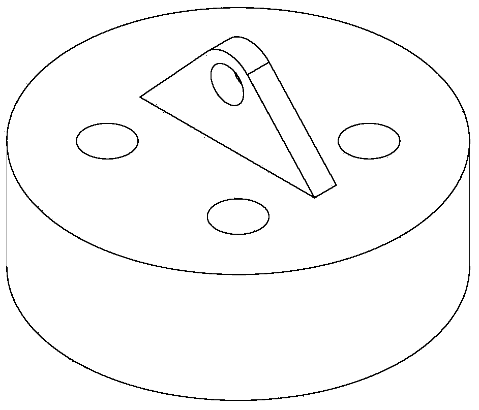
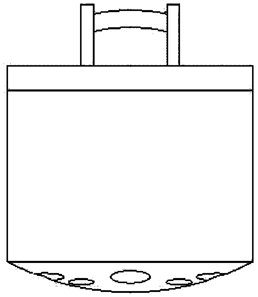
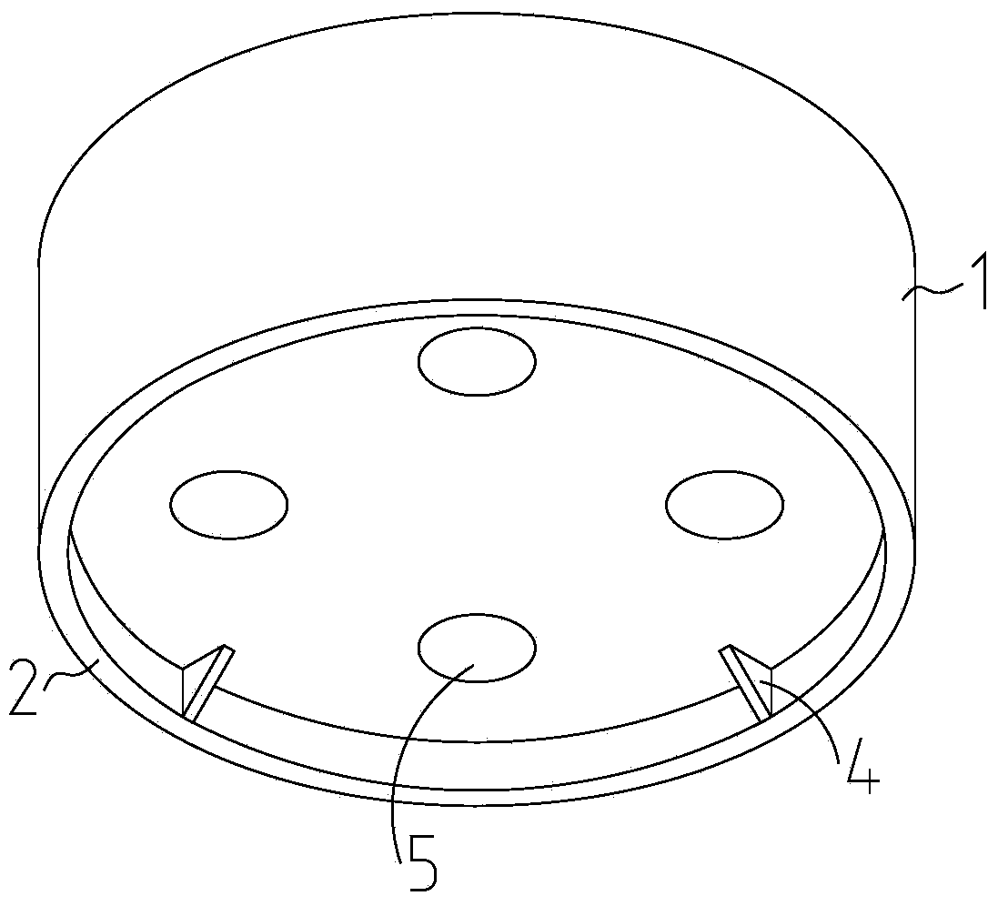
[0040] image 3 Shown is a schematic structural view of the rammer in the first embodiment of the present invention, and its front view, left view and top view can be referred to respectively Figure 4a , Figure 4b and Figure 4c . The rammer of the first embodiment includes a hammer body 1 and a ring device 2 is fixedly arranged on the hammer body 1 . The ring device 2 includes a vertical plate structure, and the bottom surface of the ring device 2 is lower than the bottom surface of the hammer ...


PUM


Abstract

The invention provides a compaction hammer and a dynamic compaction machine with the compaction hammer. The compaction hammer comprises a hammer body, wherein an annular device is fixedly or movably arranged on the hammer body and comprises a vertical plate structure, and the bottom surface of the annular device is lower than the bottom surface of the hammer body at least at the compaction landing moment. During the compaction land falling, the bottom of the annular device can be enabled to touch the ground before the bottom of the hammer body, the airwave or shock wave ejection by the annular device can be severed, so the ground debris sputtering can be effectively prevented, and the safety is improved. In addition, the compaction hammer and the dynamic compaction machine also have the advantages that the structure is simple, the manufacturing is easy, the compaction quality is reliable, the noise is low, and the like.

Description

technical field [0001] The present invention mainly relates to the technical field of dynamic ramming, in particular to a rammer and a dynamic ramming machine provided with the rammer. Background technique [0002] In construction projects, it is often necessary to use a dynamic tamping machine to tamp the ground. The dynamic tamping machine first lifts the heavy rammer to a high place, and then makes the rammer fall freely, so that it can give the foundation a strong impact and vibration, destroy the soil and compact it, which can improve the strength of the foundation and reduce the Compressibility, improving its resistance to vibration and liquefaction, eliminating collapsibility, etc. [0003] The rammer is the working part of the dynamic compactor, and the weight and drop of the tamper determine the rammer energy level of the dynamic compactor. For the dynamic tamping machine of the prior art, the rammer generally has 8-40t, the heaviest can reach 200t, and the drop d...

Claims


Application Information

Patent Timeline
Patent Type & Authority Applications(China)
IPC IPC(8): E02D3/046
Inventor 易小刚韩晓东
Owner SANY HEAVY IND CO LTD (CN)
Why Eureka
Try Eureka