
Anchor plate and anchor bolt assembly and anti-corrosion processing method of anchor bolt

A technology of assembly and anchor bolt, applied in the direction of bolts, connecting components, threaded fasteners, etc., can solve the problems of easy damage to the coating, loss of anti-corrosion ability, and inability to eliminate, achieve simple structure, prolong service life, prevent sucking effect

Active Publication Date: 2014-06-18
BEIJING GOLDWIND SCI & CREATION WINDPOWER EQUIP CO LTD
View PDF10 Cites 7 Cited by
  • Summary
  • Abstract
  • Description
  • Claims
  • Application Information

AI Technical Summary

Problems solved by technology

[0003] 1. Due to the gap between the heat shrinkable sleeve and the anchor bolt sleeve, during the construction process, as long as it rains, air and rainwater will enter the gap between the anchor bolt sleeve and the anchor bolt, forming a immersion on the anchor bolt, This poses a corrosion threat to the anchor
[0004] 2. Due to the gap between the heat shrinkable sleeve and the anchor bolt sleeve, during the 20-year service period after the fan is built, as long as there is water accumulation, rainwater and air will enter the gap between the sleeve and the anchor bolt, and Cannot be ruled out, threat to anchor bolt corrosion
[0005] 3. For this technical solution, if the anchor bolts are to be anti-corrosion, it is only suitable for coating anti-corrosion, but because the anchor bolts are subject to tensile stress during the construction process, the coating is easily damaged under the action of tensile stress, thus losing its anti-corrosion properties ability

Method used


Image

  • Anchor plate and anchor bolt assembly and anti-corrosion processing method of anchor bolt
  • Anchor plate and anchor bolt assembly and anti-corrosion processing method of anchor bolt
  • Anchor plate and anchor bolt assembly and anti-corrosion processing method of anchor bolt

Examples


Embodiment 1

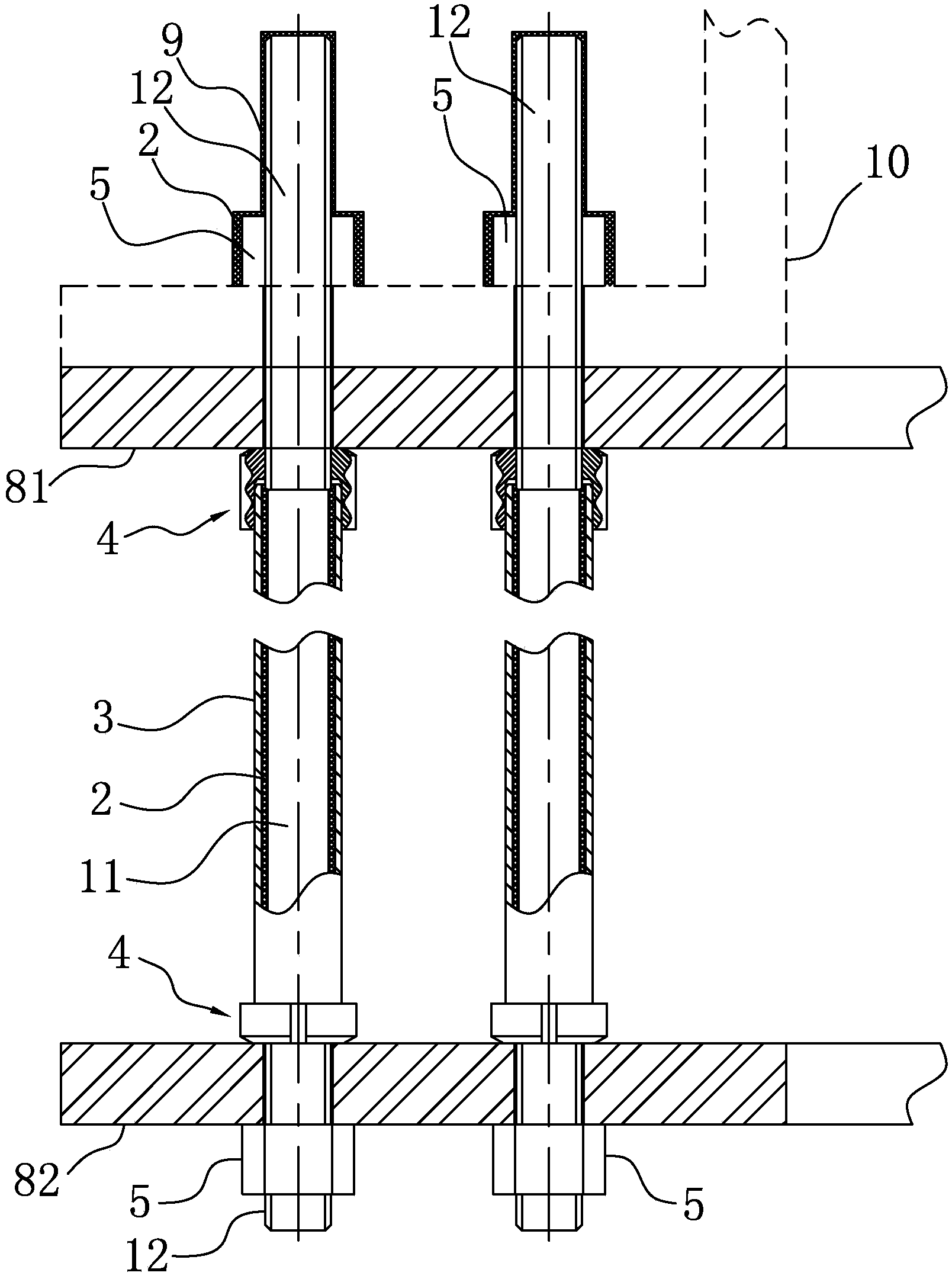
[0036] like figure 1 As shown, it is a partial cross-sectional view of the anchor plate and anchor bolt assembly of Embodiment 1 of the present invention. The anchor plate and anchor bolt assembly of this embodiment includes an upper anchor plate 81, a lower anchor plate 82 and a plurality of anchor bolts, such as image 3 As shown, the anchor bolt in this embodiment includes an anchor bolt body, and the anchor bolt body includes a middle section 11 and threaded sections 12 located on the upper and lower sides of the middle section 11. The middle section 11 is covered with a sheath 3, and the sheath 3 and the middle section 11 are provided with an anti-corrosion grease layer 2, and the threaded sections 12 on the upper and lower sides of the anchor bolt body are provided with a sealing nut 4 and a fastening nut 5, and the sealing nut 4 seals the anti-corrosion grease layer 2, see figure 1 , the upper anchor plate 81 is located between the plurality of fastening nuts 5 on the u...

Embodiment 2

[0049] The difference between this embodiment and the first embodiment lies in the sealing method between the sleeve part 42 and the sheath 3, such as Figure 5 As shown, it is a partial enlarged view of the anchor plate and anchor bolt assembly of the second embodiment, Figure 5 With Figure 4 The corresponding partial enlarged view shows the sealing structure between the sleeve part 42 and the sheath 3 in this embodiment.

[0050] In this embodiment, a first sealing ring 6 is provided between the end surface of the sheath 3 and the end surface of the threaded connection portion 41 . With such a sealing structure, the first sealing ring 6 can be conveniently and directly assembled between the end face of the sheath 3 and the threaded connection part 41 during assembly, and when the sealing nut is tightened, the first sealing ring 6 The end of the sheath 3 can be tightly sealed under the extrusion of the part 41, thereby enhancing the sealing effect on the sheath.

Embodiment 3

[0052] The difference between this embodiment and the above two embodiments lies in the sealing method between the sleeve part 42 and the sheath 3 . In this embodiment, at least one second sealing ring 7 is provided between the inner wall of the sleeve portion 42 and the outer wall of the sheath 3 . The second sealing ring 7 can be sleeved on the outer wall of the sheath 3 , and can be embedded on the inner wall of the sleeve part 42 . Compared with the sealing method of the second embodiment, the second sealing ring 7 can close the small gap between the inner wall of the sleeve part 42 and the outer wall of the end of the sheath 3 to enhance the sealing effect, and the inner wall of the sleeve part 42 A second sealing ring is provided between the outer wall of the sheath 3 to allow the sealing nut to move within a certain range on the threaded section 12 while maintaining a high sealing effect.

[0053] Preferably, as Image 6 As shown, an annular groove may be provided on ...


PUM


Abstract

The invention provides an anchor plate and anchor bolt assembly. An anchor bolt comprises an anchor bolt body, the anchor bolt body comprises a middle section and thread sections on the upper side and the lower side of the middle section, the middle section is sleeved with a protective cover, an anti-corrosion grease layer is arranged between the protective cover and the middle section, the thread sections on the upper side and the lower side of the anchor bolt body are respectively provided with a seal nut and a fastening nut, and the anti-corrosion grease layer is sealed by the seal nuts. An upper anchor plate is located between the multiple fastening nuts on the upper side and multiple seal nuts on the upper side, and a lower anchor plate is located between the multiple fastening nuts on the lower side and the multiple seal nuts on the lower side. The invention further provides the anchor bolt and an anti-corrosion processing method of the anchor bolt. Anti-corrosion protection is conducted on the anchor bolt through the anti-corrosion grease, the anti-corrosion grease is isolated from the surrounding through the seal nuts, the service life of the anti-corrosion grease is prolonged, and reliability of corrosion resistance is improved.

Description

technical field [0001] The invention relates to an anchor plate and anchor bolt assembly, and also relates to an anchor bolt and an anti-corrosion treatment method thereof. Background technique [0002] When the wind turbine tower is erected, it generally needs to be installed on the anchor plate and anchor bolt assembly. The anchor plate and anchor bolt assembly is placed in the dug hole. After pouring concrete, the anchor plate and anchor bolt assembly are integrated with the concrete, which can be well embedded in the foundation soil, so as to ensure that the installation foundation of the wind turbine is firm . Anchor bolts are used in the anchor plate and anchor bolt assembly. In the prior art, in order to prevent corrosion of the anchor bolts, dacromet is generally applied to the outside of the anchor bolts, or galvanized or galvanized on the outside of the anchor bolts. The prior art proposes a technical solution of a prestressed anchor plate and anchor bolt assembl...

Claims


Application Information

Patent Timeline
IPC IPC(8): E02D27/42E02D27/44F16B41/00
Inventor 雍飞
Owner BEIJING GOLDWIND SCI & CREATION WINDPOWER EQUIP CO LTD
Learn More