Buoyancy swing plate design adopting gravity sliding block

A slider and buoyancy technology, applied in mechanical equipment, ocean power generation, engine components, etc., can solve problems such as increasing costs

Inactive Publication Date: 2014-06-18
CHANGSHA UNIVERSITY OF SCIENCE AND TECHNOLOGY
View PDF5 Cites 5 Cited by
  • Summary
  • Abstract
  • Description
  • Claims
  • Application Information

AI Technical Summary

Problems solved by technology

However, such an approach has to face two main challenges, one of which is the need to install complex pumping and irrigation devices on the swing plate, which increases the cost of installation and maintenance; the other is that the sealing of the swing plate is raised Higher requirements to ensure the normal operation and safety of the device, while anti-corrosion and anti-fog also need attention

Method used


Image

  • Buoyancy swing plate design adopting gravity sliding block
  • Buoyancy swing plate design adopting gravity sliding block
  • Buoyancy swing plate design adopting gravity sliding block

Examples


Embodiment 1

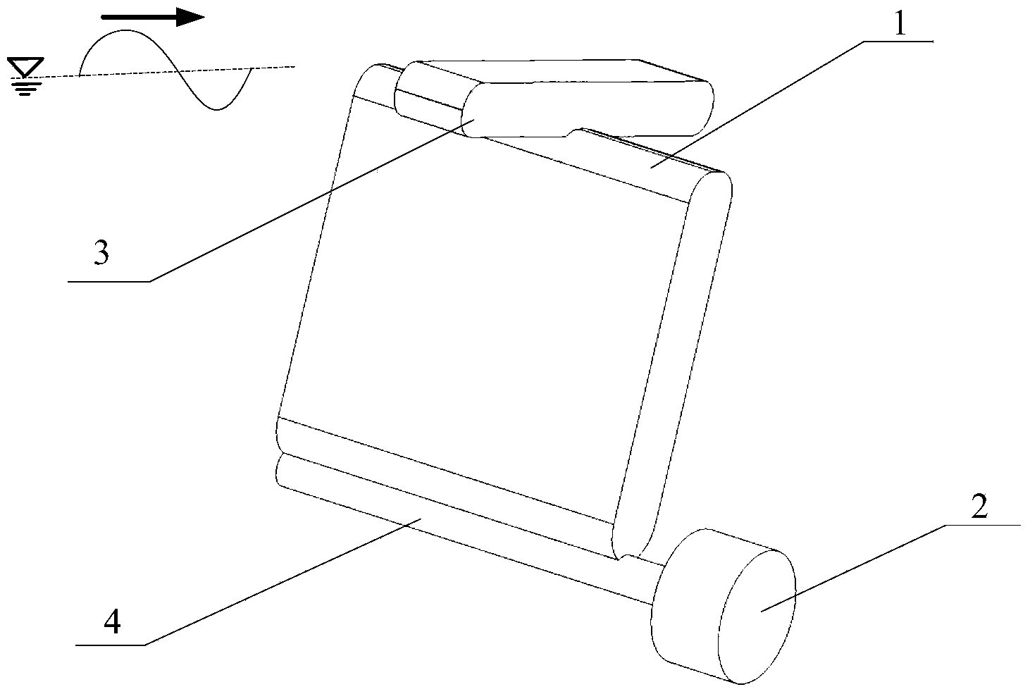
[0020] Such as figure 1 As shown, the pendulum plate 1 is fixed by the rotating shaft 4, and has a degree of freedom in one direction. The rotating shaft 4 is connected to the generator 2, and the pendulum plate 1 faces the incoming wave direction;

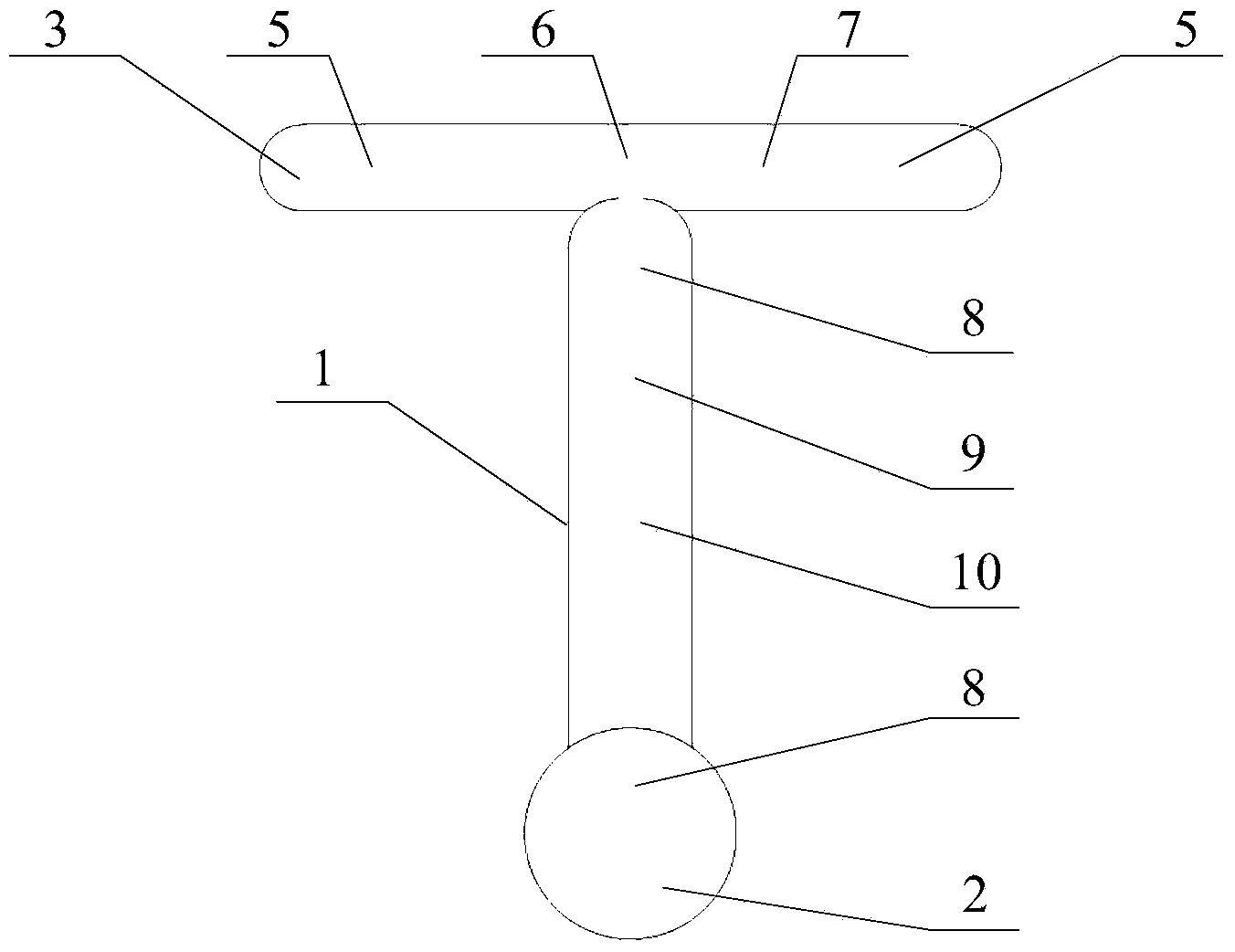
[0021] Such as figure 2 As shown, a gravity slider 10 and a sliding shaft 9 are installed inside the pendulum plate 1, and protective gaskets 8 are installed at both ends of the sliding shaft 9; similarly, a gravity slider 6 is also installed inside the slider cabin 3 And the sliding shaft 7, the two ends of the sliding shaft 7 are equipped with protective pads 5.

[0022] Such as image 3 As shown, the sliding shaft 9 inside the pendulum plate 1 is in the middle position, and the slider 10 can move along the sliding shaft 9 in a direction away from and close to the rotating shaft 4. The spacers 8 are arranged on the top and bottom of the sliding shaft 9 respectively. 9 two ends are connected with pendulum plate 1.

[0023] S...


PUM


Abstract

The invention belongs to the field of novel regenerative energy technologies and coastal structures, and particularly relates to a buoyancy swing plate design adopting a gravity sliding block. The buoyancy swing plate design comprises a swing plate, a generator, a rotating shaft, the sliding block, a gasket and a sliding shaft, wherein the swing plate, the generator and the rotating shaft are arranged on an ocean engineering infrastructure on a seabed; a sliding block bin is positioned on the upper part of the swing plate; the sliding block, the gasket and the sliding shaft are distributed in the swing plate and the sliding block bin; the buoyancy swing plate design is characterized in that the buoyancy swing plate can do reciprocating rotation under the action of waves; the swing plate and the sliding block in the sliding block bin can reach different positions along the sliding shaft under the action of the motion of the swing plate, so that the gravity center position, the rotation inert and the natural period of the swing plate can be changed, resonance between the waves and the swing plate is promoted, and the wave energy conversion efficiency is improved. The design disclosed by the invention is suitable for irregular waves in a natural environment under a real sea condition, can stimulate the resonance effect and improve the wave energy capturing efficiency, is simple in form, is feasible and is higher in reliability.

Description

technical field [0001] The invention belongs to the field of novel renewable energy technology and coastal structures, in particular to a design of a buoyancy pendulum pendulum plate adopting a gravity slider. Background technique [0002] In my country's vast sea area and surrounding islands, marine renewable energy reserves are very rich, including wave energy, tidal energy, ocean current energy, temperature difference energy, and salt difference energy, etc., which have extremely high development and utilization prospects. Among them, wave energy is the highest-grade ocean energy because it has the least impact on the environment and exists in the form of mechanical energy during the development process. Wave power generation is the main way to utilize wave energy. There are many types of wave energy utilization devices, and there are more than a thousand invention patents related to wave energy conversion devices. These devices are mainly based on the following basic me...

Claims


Application Information

Patent Timeline
Patent Type & Authority Applications(China)
IPC IPC(8): F03B13/14
CPCY02E10/38Y02E10/30
Inventor 彭伟
Owner CHANGSHA UNIVERSITY OF SCIENCE AND TECHNOLOGY
Why Eureka
Try Eureka