Gravity energy storing system relying on massif

An energy storage system, gravity technology, applied in the direction of machine/engine, mechanical equipment, engine, etc., can solve the problems of high system complexity, large useful land area, limited practical value, etc., achieve mature technology, long working life, realize The effect of uniform output of power

Inactive Publication Date: 2014-06-18
TIANJIN UNIV
View PDF5 Cites 47 Cited by
  • Summary
  • Abstract
  • Description
  • Claims
  • Application Information

AI Technical Summary

Problems solved by technology

However, this scheme occupies a large area of ​​useful land, has many geographical constraints, a large amount of engineering, and the overall efficiency is not high (about 80% for one-way, about 60% for two-way), and the maintenance cost is high, so the practical value is limited.
More skilled technicians may further imagine that braking is not performed in the first part of the glide stroke, but arresting cables are only installed in the straight section at the end of the sloped rail, and the kinetic energy is converted into electrical energy through the braking of the arresting cables, then the total efficiency can be obtained. Increased to about 70%, but with high system complexity

Method used


Image

  • Gravity energy storing system relying on massif
  • Gravity energy storing system relying on massif
  • Gravity energy storing system relying on massif

Examples


Embodiment 1

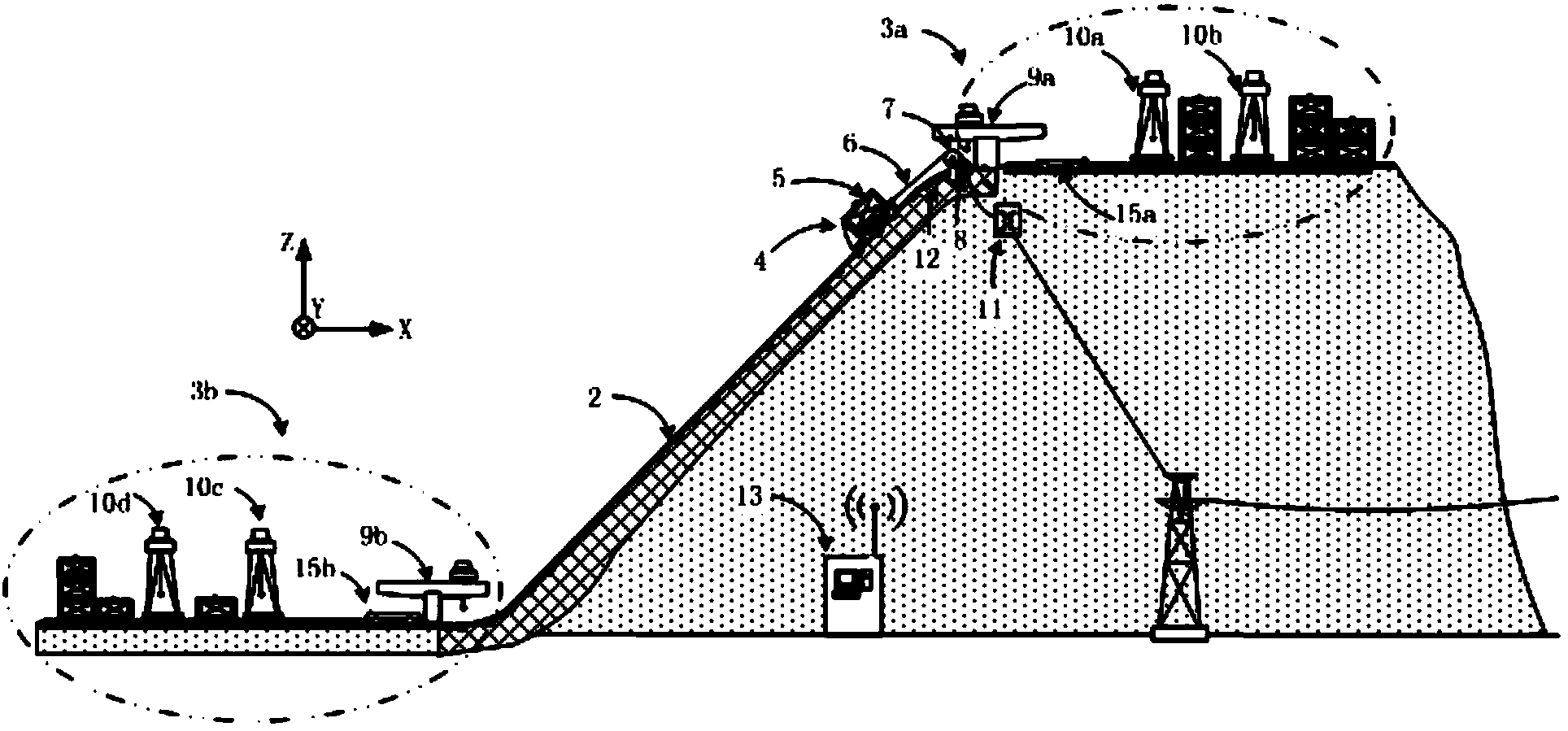
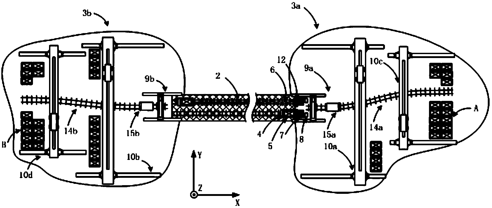
[0035] see figure 1 and figure 2 , a gravity energy storage system relying on mountains, its basic layout is: a mountain with a certain slope and height 1 . At least two inclined rails are laid on the hillside of the mountain body 1. In this embodiment, each inclined rail is formed by a section of continuous rail 2. The continuous rail 2 adopts standard railway rails, and the gauge and sleepers are properly adjusted as required. The gap between the continuous rail 2 and the slope of the mountain is poured with reinforced concrete or supported with a reinforced concrete column. A stacking platform is respectively constructed at both ends of the continuous rail 2, namely a high-altitude stacking platform 3a at the top of the mountain and a low-altitude stacking platform 3b at the foot of the mountain. Run a trailer 4 on each section of continuous rail 2 to realize the lifting and lowering of the standardized weight 5. The continuous rail 2 is generally laid in a straight lin...

Embodiment 2

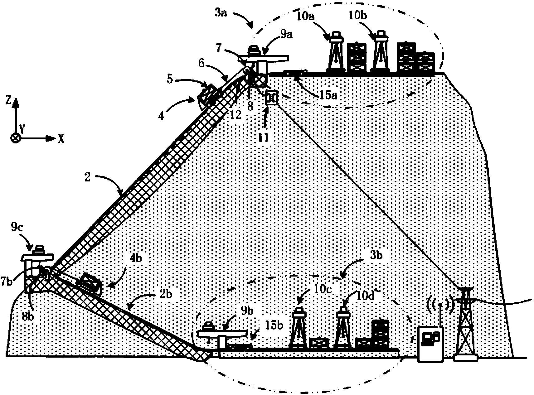
[0054] The difference with embodiment 1 is that: 1) each inclined rail is made up of two sections of continuous rails 2, 2b, and trailers 4 and 4b travel on them respectively. 2) There is an intermediate reloading platform on the mountainside, on which intermediate reloading equipment 9c and power lifting and power generation devices are installed. The structure of the power generation device is the same as that of the power lifting and power generation device in Embodiment 1, including a motor-generator integrated machine 8b, a cable winch 7b and a trailer 4b; the intermediate transfer device 9c is responsible for transferring the standardized weight 5 from the trailer 4 to the trailer 4b, or reverse reprint. This embodiment is more suitable for the situation that there are multiple connected but different slopes on the mountain body.

[0055] In summary, the present invention has at least two stacking platforms, wherein at least one of the stacking platforms is built at a h...


PUM


Abstract

The invention discloses a gravity energy storing system relying on a massif. The gravity energy storing system comprises a high-altitude stacking platform, a low-altitude stacking platform, a plurality of standard weights, electric power increasing and generating devices and a control system. The position between the high-altitude stacking platform and the low-altitude stacking platform is paved with at least two inclined tracks, each inclined track is provided with at least one section of continuous track and each section of continuous track is provided with one set of electric power increasing and generating device. Each set of electric power increasing and generating device comprises a trailer, a cable, a cable winch and an electric generating all-in-one machine, wherein the trailer is arranged on the corresponding continuous track and connected with one end of the cable, the cable winch is installed on the edge of the platform at the end of the corresponding continuous track, and the cable winch is connected with the electric generating all-in-one machine. The control system controls the working conditions of transferring, transporting and stacking equipment and the electric power generating all-in-one machine. The gravity energy storing system is high in efficiency, low in cost, small in occupied space and high in safety coefficient.

Description

technical field [0001] The invention relates to the technical field of energy storage, and is an efficient energy storage / release system for converting electric energy into gravitational potential energy for storage and converting stored gravitational potential energy into electric energy. Background technique [0002] In recent years, my country's industrial electricity consumption has grown rapidly, and the difference between the peak and valley of electricity consumption has continued to increase. On the other hand, although renewable energy (wind energy, solar energy, tidal current energy, etc.) is green and clean, it usually has the disadvantages of poor regularity and large fluctuations, making it difficult to keep in line with the real-time trend of electricity demand. Although my country's installed capacity of renewable energy continues to expand, the problems of tight power supply and difficulties in power grid peak regulation have become increasingly prominent. ...

Claims


Application Information

Patent Timeline
Patent Type & Authority Applications(China)
IPC IPC(8): F03G3/00
Inventor 罗振军黄田梅江平牛文铁杨帆
Owner TIANJIN UNIV
Why Eureka
Try Eureka