
Dynamic signal phasor measurement method based on time domain quasi-synchronization

A time-domain quasi-synchronous and dynamic signal technology, applied in the direction of measuring devices, measuring electrical variables, phase angles between voltage and current, etc., can solve the problem of being easily affected by harmonics and noise components, low precision, and spectrum leakage And other issues

Active Publication Date: 2014-06-18
HUNAN UNIV
View PDF5 Cites 33 Cited by
  • Summary
  • Abstract
  • Description
  • Claims
  • Application Information

AI Technical Summary

Problems solved by technology

The zero-crossing detection method is a relatively intuitive synchrophasor measurement method. It only needs to compare the zero-crossing moment of the measured power frequency signal with a certain time standard to obtain the phase angle difference; the principle of the zero-crossing detection method is simple. Easy to implement, but its accuracy is not high, and it is easily affected by harmonics and noise components
When there is no frequency deviation in the grid, the DFT algorithm can accurately measure the amplitude and phase of the signal, and its calculation accuracy is not affected by the constant DC component and the whole harmonic component; but when the grid frequency has a deviation, due to Spectrum leakage caused by asynchronous sampling, the accuracy of phasor measurement will drop rapidly

Method used


Image

  • Dynamic signal phasor measurement method based on time domain quasi-synchronization
  • Dynamic signal phasor measurement method based on time domain quasi-synchronization
  • Dynamic signal phasor measurement method based on time domain quasi-synchronization

Examples


Embodiment Construction

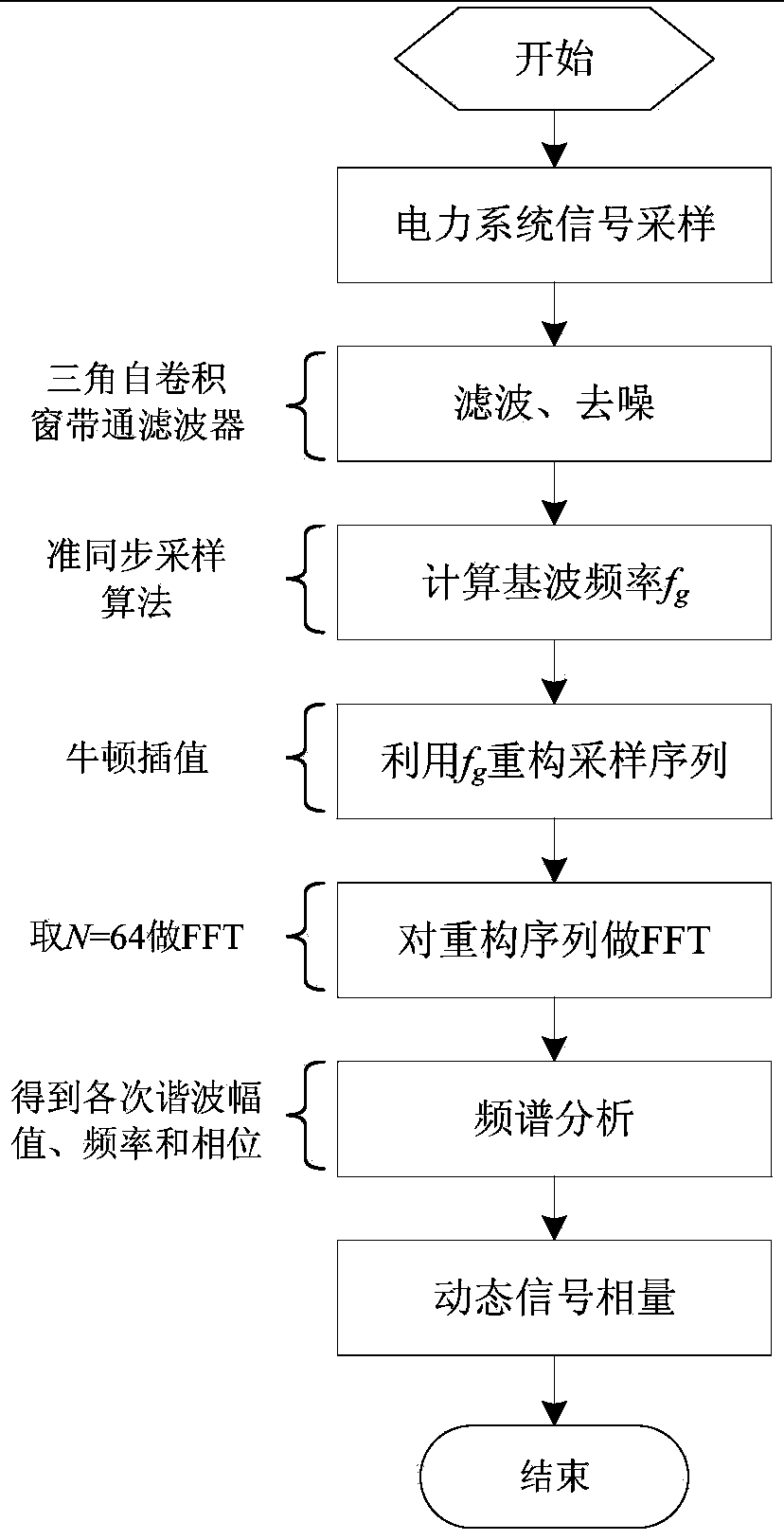
[0046] The program flow of the present invention to realize the harmonic analysis and measurement method based on time domain quasi-synchronization is as follows: figure 1 shown.

[0047] Such as figure 1 As shown, the first step is to use the power quality analysis system to sample the input signal to obtain N c samples, N c is a natural number, f s is the sampling frequency.

[0048] In the second step, use a triangular self-convolution window bandpass filter to collect the N c The samples are filtered and denoised. The parameters of the triangular self-convolution window bandpass filter are: triangular self-convolution window bandpass filter, the lower stopband edge frequency is 40Hz, the lower passband edge frequency is 46Hz, the upper passband edge frequency is 54Hz, the upper stopband The edge frequency is 60Hz, the passband ripple is 0.01, and the stopband ripple is 0.1.

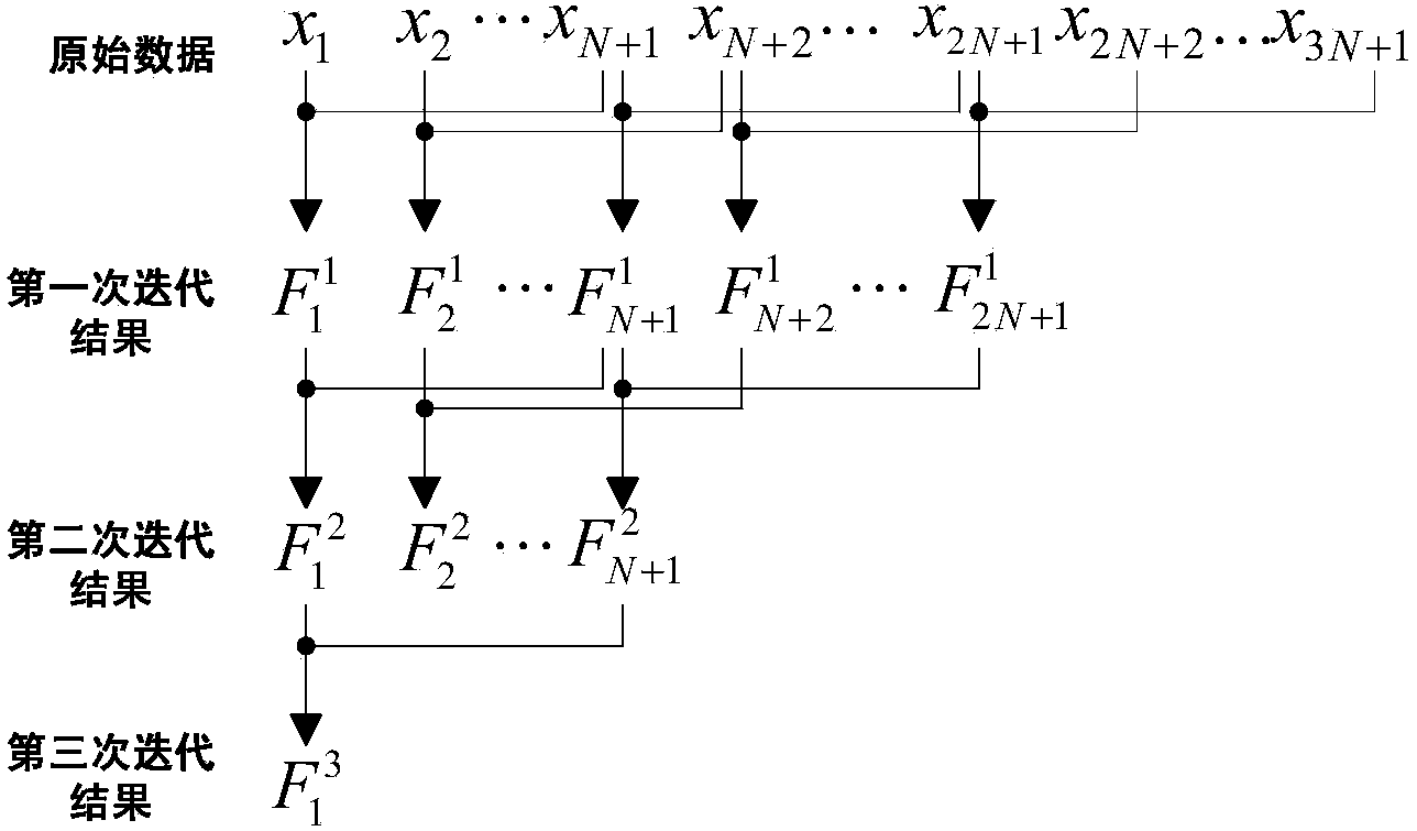
[0049]The third step is to use the quasi-synchronous sampling algorithm to iterate the filt...


PUM


Abstract

The invention discloses a dynamic signal phasor measurement method based on time domain quasi-synchronization. The dynamic signal phasor measurement method based on the time domain quasi-synchronization comprises the following steps: estimating the fundamental wave frequency of a sampled signal by a time domain quasi-synchronization sampling algorithm; carrying out time domain quasi-synchronization on the sampled signal by the estimated value of the fundamental wave frequency; reconstructing a quasi-synchronization sampling sequence by Newton interpolation; carrying out frequency domain analysis on the reconstructed quasi-synchronization sampling sequence by FFT (fast Fourier transform) to obtain a dynamic signal phasor measurement result. According to the method, the influence on the measurement precision of the traditional phasor measurement method by frequency spectrum leakage caused by nonsynchronous sampling is avoided. The computation complexity of the dynamic signal phasor measurement method based on the time domain quasi-synchronization is smaller than the computation complexity of the traditional phasor measurement method based on the discrete Fourier transform, and the dynamic signal phasor measurement method based on the time domain quasi-synchronization is easy to realize in an embedded system.

Description

technical field [0001] The invention relates to the field of signal phasor measurement, in particular to a dynamic signal phasor measurement method based on time domain quasi-synchronization. Background technique [0002] With the widespread use of nonlinear loads such as power electronic devices and semiconductor devices, power quality problems emerge in endlessly. How to measure and analyze the actual situation of the power system in real time, so as to improve the power quality, has become the focus and hot spot in the field of power system research in recent years. [0003] At present, the voltage and current in the power system are time variables that change sinusoidally with time, and can be expressed by phasors. However, IEEE Standard 1344-1995 defines the phasor on the premise that under steady-state conditions, that is, the amplitude, frequency and phase angle of the signal remain unchanged, and at the rated frequency, the instantaneous measurement value of the pha...

Claims


Application Information

Patent Timeline
Patent Type & Authority Applications(China)
IPC IPC(8): G01R25/00G01R23/165
Inventor 温和滕召胜王康孟卓黎福海郭斯羽金冉戴慧芳沈凤文张海焕吴禹李峰
Owner HUNAN UNIV
Learn More