Capacitive element, capacitor array, and a/d converter

A technology of capacitive elements and capacitors, applied in electrical components, tubular capacitors, analog-to-digital converters, etc., can solve problems such as increasing manufacturing costs

Active Publication Date: 2014-06-18
SOCIONEXT INC
View PDF15 Cites 4 Cited by
  • Summary
  • Abstract
  • Description
  • Claims
  • Application Information

AI Technical Summary

Problems solved by technology

[0039] Among capacitive elements, PIP capacitors have the problem that they cannot be formed by standard logic manufacturing processes, thus requiring additional manufacturing steps, which increases manufacturing costs

Method used


Image

  • Capacitive element, capacitor array, and a/d converter
  • Capacitive element, capacitor array, and a/d converter
  • Capacitive element, capacitor array, and a/d converter

Examples


Embodiment Construction

[0070] Before describing in detail embodiments of capacitive elements, capacitor arrays, and A / D converters, reference will be made to Figure 1A to Figure 5 Examples detailing capacitive elements, capacitor arrays, A / D converters and their problems.

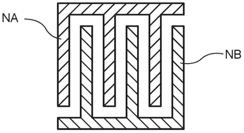
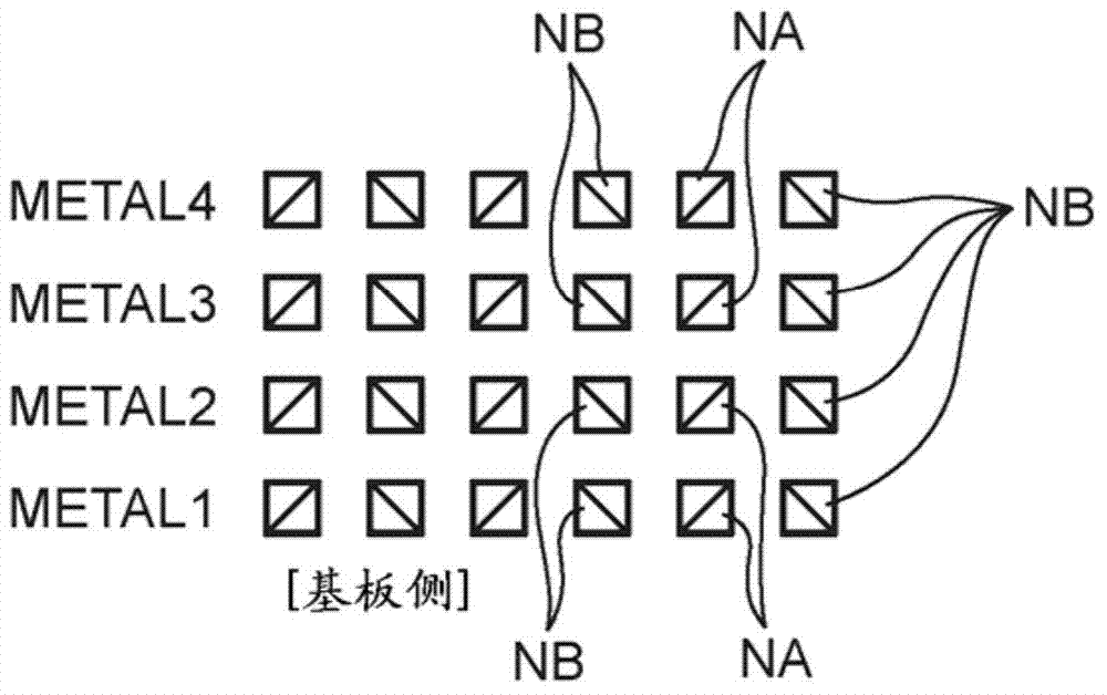
[0071] Figure 1A with Figure 1B is a diagram showing an example of a comb-shaped capacitive element. Figure 1A shows a top view, and Figure 1B A cross-sectional view is shown. exist Figure 1A with Figure 1B , reference numeral NA denotes a first electrode (first node) of the capacitive element, NB denotes a second electrode (second node) of the capacitive element, and METAL1 to METAL4 denote respective layers of wiring layers (metal wiring layers).

[0072] In other words, if Figure 1A As shown, the first electrodes NA and the second electrodes NB are arranged alternately, and are capacitively coupled to each other to form a capacitive element (comb-shaped capacitive element). In addition, if Figure 1B As shown, in ...


PUM


Abstract

The invention provides a capactive element, a capatictor array and an A / D coverter. A capacitive element includes first electrodes and second electrodes that are alternately arranged in a concentric form. Each of the first electrodes and the second electrodes is formed with closed loop form, in at least one wiring layer provided on or above a substrate.

Description

technical field [0001] Embodiments discussed herein relate to capacitive elements, capacitor arrays and A / D converters. Background technique [0002] In recent years, A / D converters are widely used in various fields. More specifically, as A / D converters with relatively high resolution, successive approximation type A / D converters and delta-sigma (delta-sigma) A / D converters are known. Such A / D converters include, for example, switched capacitor circuits, and are widely used in the form of CMOS (Complementary Metal Oxide Semiconductor) integrated circuits. [0003] As performance indicators of the A / D converter, there are, for example, linearity, offset, and gain errors. However, the advantages of the conversion characteristics of the A / D converter largely lie in the matching of capacitive elements, the control of voltage dependence, and the like in most cases. Therefore, in order to realize an A / D converter with high conversion accuracy, it is preferable to apply a capaci...

Claims


Application Information

Patent Timeline
Patent Type & Authority Applications(China)
IPC IPC(8): H01L23/522H03M1/12
CPCH03M1/12H01G4/28H01G4/38H01G4/012
Inventor 有贺健太
Owner SOCIONEXT INC
Why Eureka
Try Eureka