Secondary battery
A secondary battery and current collector foil technology, which is applied in the direction of secondary batteries, batteries, battery electrodes, etc., can solve the problems of shortened driving distance, reduced capacity of lithium-ion secondary batteries, and inability to exert full output, etc., to achieve high output performance Effect
- Summary
- Abstract
- Description
- Claims
- Application Information
AI Technical Summary
Problems solved by technology
Method used
Image

Examples
no. 1 example
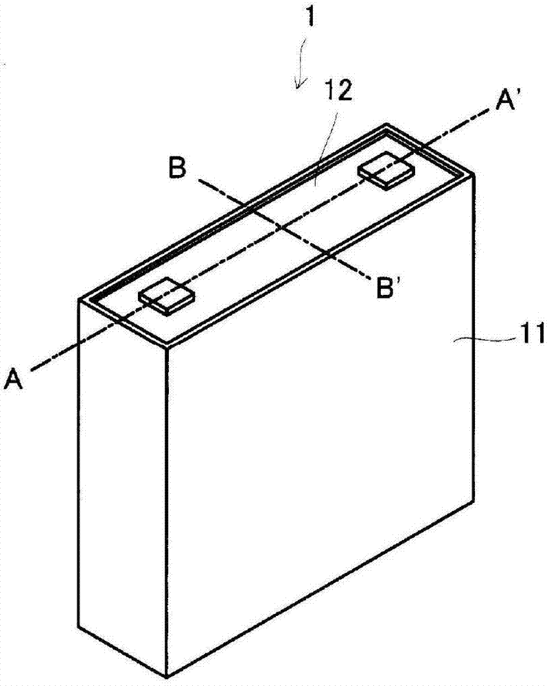
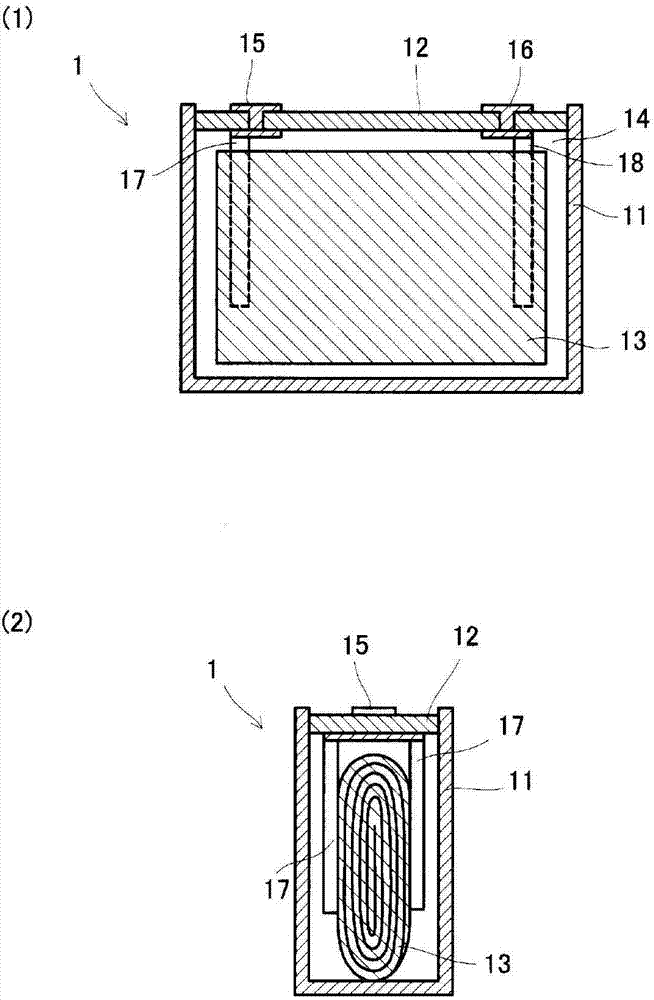
[0040] use figure 1 and figure 2 A first embodiment of the present invention will be described. figure 1 is a perspective view showing a secondary battery (lithium ion secondary battery) according to the present embodiment; figure 2 (1) is shown along the figure 1 A cross-sectional view of the A-A' line, (2) is shown along the figure 1 Cutaway view of line BB'.
[0041] The secondary battery 1 of the present invention is mounted in, for example, an electric vehicle. The secondary battery 1 includes a substantially rectangular parallelepiped case 11 and a cover portion 12 disposed in an opening portion of the case 11 for sealing the case 11 . like figure 2 As shown, the housing 11 accommodates the electrode body 13 . In addition, an electrolytic solution 14 is injected into the casing 11 , and the electrode body 13 is immersed in the electrolytic solution 14 . The electrode body 13 is formed by laminating and winding a positive electrode plate and a negative electrod...
no. 2 example
[0068] In the above-mentioned first embodiment, the current collector foil 33 and the second positive electrode layer 32 are electrically connected by cutting out the protruding portion 34, but in this embodiment, as Figure 4 As shown, the difference is that the current collector foil 33A and the second positive electrode layer 32A are electrically connected by the conductive member 35A. In addition, in this embodiment, for convenience of description, the current collector foil and the positive electrode active material layer on the side of the separator are omitted.
[0069] In this embodiment, after the first positive electrode layer 31A and the second positive electrode layer 32A are formed on the current collector foil 33A, the rod-shaped conductive member 35A is inserted from the surface side of the second positive electrode layer 32A. The conductive member 35A is a rod-shaped member longer than the thickness of the first positive electrode layer 31A. For the conductive m...
no. 3 example
[0073] In the above-mentioned second embodiment, the rod-shaped conductive member 35A is inserted from the surface side of the second positive electrode layer 32A to form a conductive path through the conductive member 35A, but in this embodiment, as Figure 5 As shown, the difference from the second embodiment is that a rod-shaped conductive member 35B is inserted from the current collector foil 33B side to form a conductive path through the conductive member 35B. In this embodiment, for convenience of description, the current collector foil and positive electrode active material layer on the side of the separator are omitted.
[0074] like Figure 5 As shown in (1), in this embodiment, after the first positive electrode layer 31B and the second positive electrode layer 32B are formed on the current collector foil 33B, the rod-shaped conductive member 35B is inserted through the opening 36B formed on the current collector foil 33B. . The conductive member 35B is the same as...
PUM
| Property | Measurement | Unit |
|---|---|---|
| Average particle diameter | aaaaa | aaaaa |
| Thickness | aaaaa | aaaaa |
| Average particle diameter | aaaaa | aaaaa |
Abstract
Description
Claims
Application Information
 - R&D
- Intellectual Property
- Life Sciences
- Materials
- Tech Scout
- Unparalleled Data Quality
- Higher Quality Content
- 60% Fewer Hallucinations
Browse by: Latest US Patents, China's latest patents, Technical Efficacy Thesaurus, Application Domain, Technology Topic, Popular Technical Reports.
© 2025 PatSnap. All rights reserved.Legal|Privacy policy|Modern Slavery Act Transparency Statement|Sitemap|About US| Contact US: help@patsnap.com