Forming method of power supply connector

A power connector and molding method technology, applied in the assembly/disassembly of contacts, manufacturing of contacts, etc., can solve the problems of inconvenient waste recycling, affecting product appearance, poor contact, etc.

Inactive Publication Date: 2014-06-18
RIIDEA
View PDF3 Cites 5 Cited by
  • Summary
  • Abstract
  • Description
  • Claims
  • Application Information

AI Technical Summary

Problems solved by technology

[0003] The indispensable component inside the power socket is at least one metal pin. Traditional metal pins can be divided into hollow and solid. Figure 18 As shown, the hollow metal terminal is punched out of a pre-shaped sheet on a metal plate, such as a copper plate, and then one end of it is crimped into a cylindrical contact portion A, and the other end extends a flat terminal portion B. The contact Part A and terminal part B are integrally formed instead of riveted. The lack of the hollow metal terminal is that due to its crimping, it is very important to control the force during the rolling process. If the force is too large or the force is applied If the force is insufficient, the two sides cannot be closely joined at the joint position, which will easily lead to warping or deformation of the plate, resulting in an increase in product failure rate, and the structural strength of the hollow metal terminal is poor. When plugged into the opposite type of electrical connector, It is easy to cause metal terminals to be deformed, twisted or broken by force. In addition, seams will be formed at the front edge of the flaky curled pin, which will seriously affect the appearance of the product.
[0004] In view of the lack of the aforementioned hollow metal terminals, relevant industry companies have proposed a power socket with solid metal terminals, such as Figure 19 As shown, the base C of the power socket has a solid terminal D and a terminal E, the solid terminal D is penetrated in the base C, and the solid terminal D is provided with a retaining ring D1 that is against the front side of the base C. The solid terminal D protrudes to the rear side of the base C, and there is a connection end D2, and the terminal E is riveted with the connection end D2 of the solid terminal D, so that the solid terminal D is fixed in the base C, because the solid terminal D is Manufactured by turning, because the retaining ring D1 has a larger outer diameter than the solid terminal D, so the metal material must be at least equal to the outer diameter of the retaining ring D1 before it can be turned to form the solid terminal D and retaining ring D1. Waste materials account for about 40% of the whole, resulting in waste of materials and inconvenience in recycling waste materials. In this way, the production cost of the solid terminal D will be greatly increased, and riveting is required, which not only increases the riveting equipment and processing costs, and if the connecting end D2 of the solid terminal D and the terminal E are loose due to insufficient riveting strength or damage by external force, it will lead to high temperature, poor contact, sparks or falling off, which will seriously affect the product. safe to use
[0005] However, the metal pins inside the current power connectors, whether they are hollow or solid terminals, must spend a lot of time in the molding process during the manufacturing process. The hollow terminals have poor structural strength, are easy to bend, and deform. Or broken, the forming winding operation is quite troublesome, which will easily lead to an increase in the product failure rate; solid terminals must be time-consuming and labor-intensive turning processing, and produce a lot of processing waste that is difficult to handle, resulting in a waste of resources

Method used


Image

  • Forming method of power supply connector
  • Forming method of power supply connector
  • Forming method of power supply connector

Examples


Embodiment Construction

[0053] In order to achieve the above-mentioned purpose and effect, the technical means adopted in the present invention, its structure, and the method of implementation are hereby illustrated in detail with respect to the preferred embodiments of the present invention. Its features and functions are as follows, in order to fully understand.

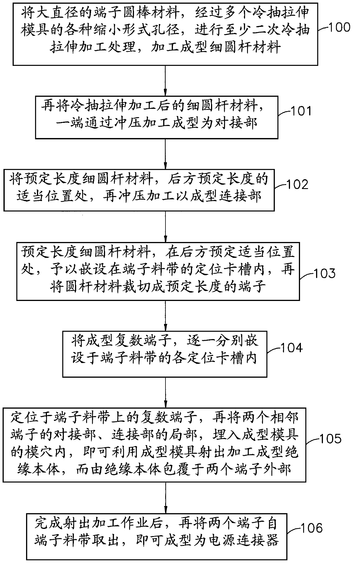
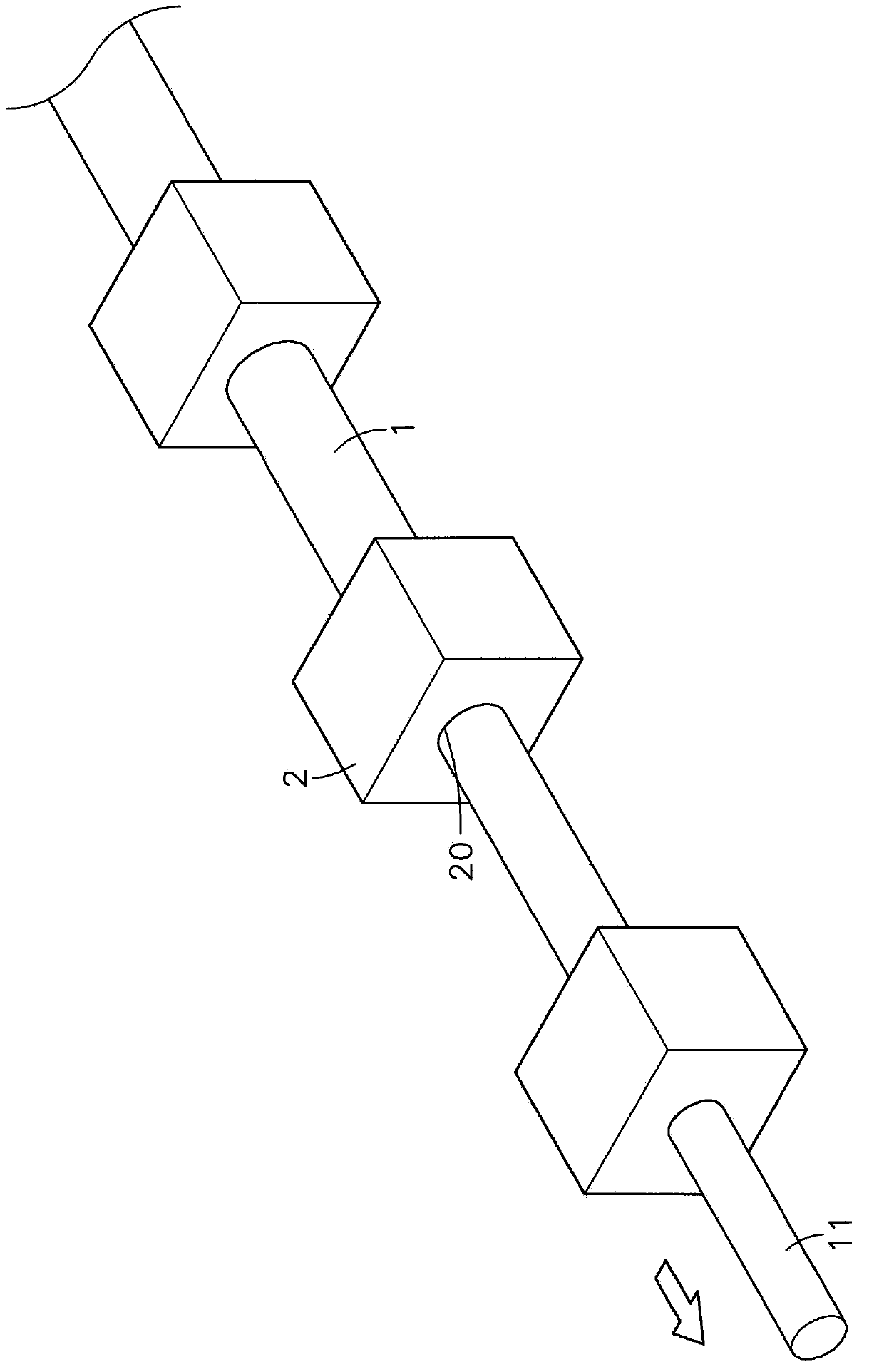
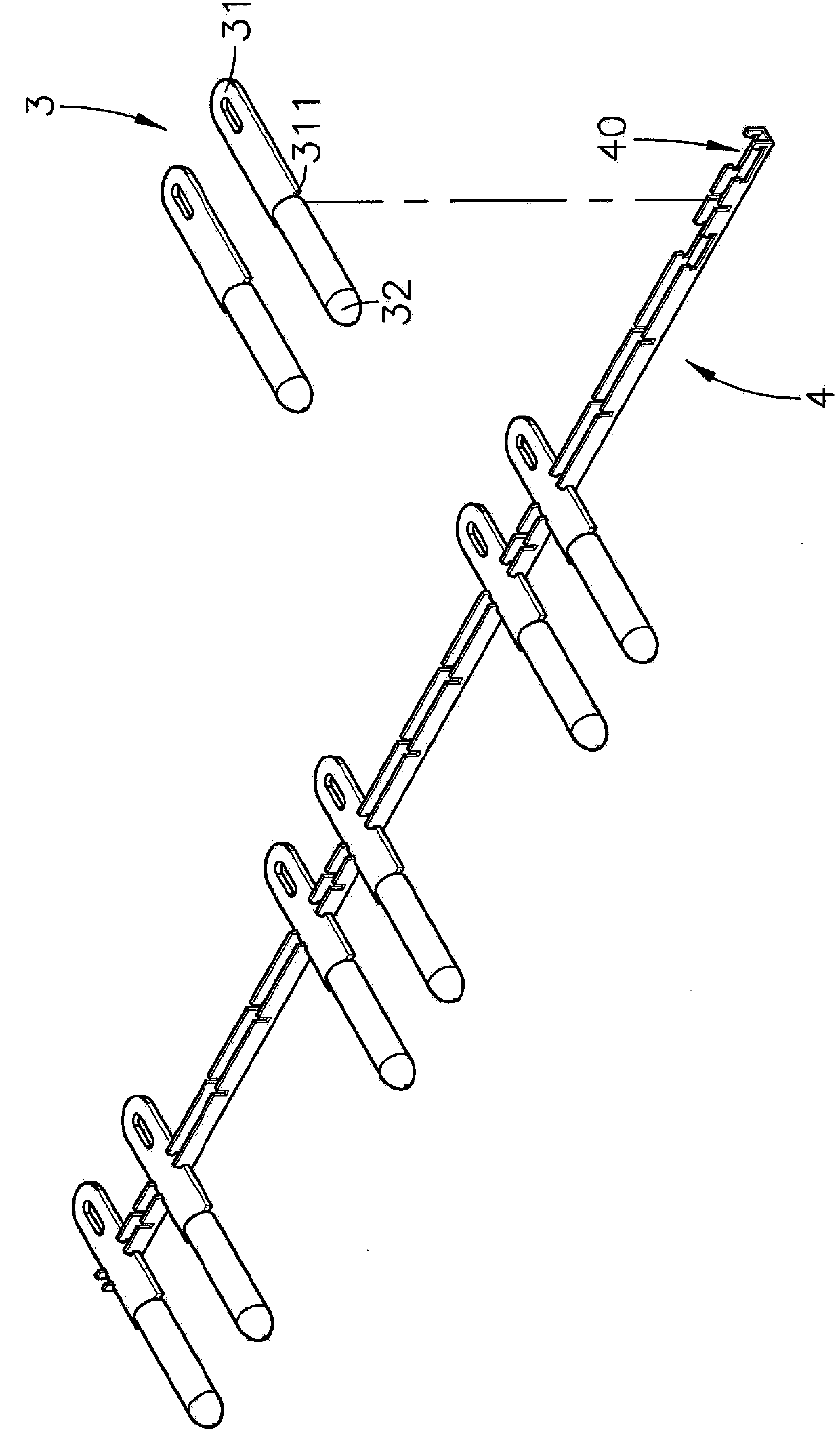
[0054] see figure 1 , figure 2 , image 3 , Figure 4 , Figure 5 ,Figure 6, Figure 7 Shown are the flow chart of the present invention, the three-dimensional appearance diagram of the terminal cold drawing stretching process, the three-dimensional exploded view of the terminal strip, the three-dimensional appearance diagram of the molding die, the top section view of the molding die, the three-dimensional appearance diagram of the insulating body, The three-dimensional appearance diagram of the power connector, it can be clearly seen from the figure that the forming steps of the power connector of the present invention are:

[00...


PUM


Abstract

The invention discloses a forming method of a power supply connector. The forming method comprises the forming steps of processing and forming slender round bar materials by carrying out at least twice cold drawing and stretching processing treatments on terminal round bar materials; punching and forming one ends of the slender round bar materials into terminal butt-joint parts; punching, processing and forming appropriate positions at the rear parts of the slender round bar materials into connecting parts; respectively embedding the slender round bar materials in each locating clamping groove of a terminal material strap one by one, and cutting the slender round bar materials into terminals in preset lengths; respectively locating a plurality of terminals in each locating clamping groove of the terminal material strap after the terminals are formed by repeating the processing mode; embedding the local parts of the butt-joint parts and the connecting parts of two adjacent terminals on the terminal material strap in a die cavity of a forming die, ejecting, processing and forming insulation bodies at the outer parts of the two terminals by utilizing plastics, and separating the two terminals from the terminal material strap; forming the power supply connector after the forming die is removed. According to the forming method disclosed by the invention, the purposes of increasing the working efficiency and reducing the manufacturing cost can be achieved.

Description

technical field [0001] The invention relates to a forming method of a power connector, especially a method that can process and quickly form a power connector through consistent operations. A round bar is processed by cold drawing and stamping to form a plurality of terminals, and then two adjacent terminals are formed. The outside of the terminal is injection-molded with a molding die to form an insulating body, and the power connector is quickly processed and formed. Background technique [0002] Power sockets are widely used in electrical products, such as portable audio or video projectors (such as VCD, DVD, etc.), and information products, such as computers, notebook computers, mobile phones, etc. The product's power socket and mains socket enable the product to obtain power for user operation. [0003] The indispensable component inside the power socket is at least one metal pin. Traditional metal pins can be divided into hollow and solid. Figure 18 As shown, the hol...

Claims


Application Information

Patent Timeline
Patent Type & Authority Applications(China)
IPC IPC(8): H01R43/16H01R43/24
Inventor 李隆禧
Owner RIIDEA
Why Eureka
Try Eureka