Cable bending device

A cable and wire clamping technology, applied in the field of cable bending devices, can solve the problems of easily damaged cables, difficulty in bending cables, and high labor intensity of staff, and achieves the elimination of potential safety hazards, a simple structure, and a manufacturing cost. low effect

Active Publication Date: 2016-07-13
STATE GRID CORP OF CHINA +1
View PDF8 Cites 1 Cited by
  • Summary
  • Abstract
  • Description
  • Claims
  • Application Information

AI Technical Summary

Problems solved by technology

[0005] The purpose of the present invention is to provide a cable bending device to solve the problems in the prior art that the cable is difficult to bend, the cable is easily damaged, and the labor intensity of the staff is high.

Method used


Image

  • Cable bending device

Examples


Embodiment Construction

[0018] The embodiments of the present invention will be described in detail below with reference to the accompanying drawings, but the present invention can be implemented in many different ways defined and covered by the claims.

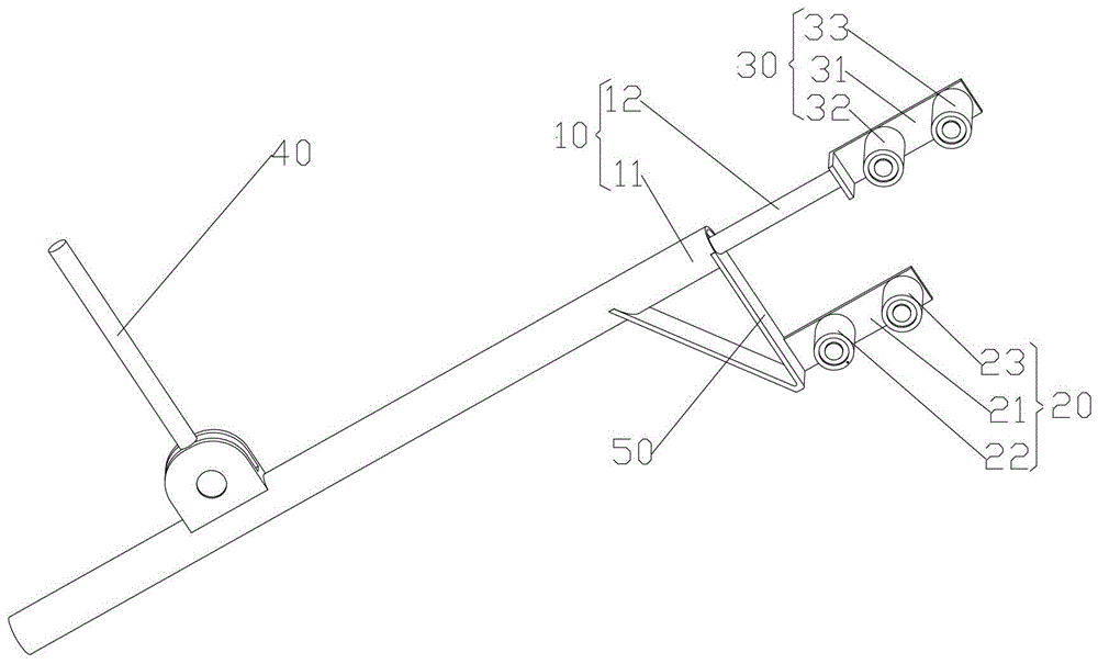
[0019] The invention provides a bending device for cables. Such as figure 1 As shown, the bending device includes: a rod part 10, the rod part 10 includes a sleeve rod 11 and a telescopic rod 12, and the telescopic rod 12 is movably arranged in the sleeve rod 11; the first wire clamping part 20 has a first wire clamping groove, and the A clamping part 20 is connected to the first end of the sleeve rod 11; a second clamping part 30 has a second clamping slot, and the second clamping part 30 is connected to the first end of the telescopic rod 12; the driving part is fixed at one end It is arranged on the sleeve rod 11 , and the other end is connected with the telescopic rod 12 , and the driving part drives the telescopic rod 12 to move along the axia...


PUM


Abstract

The invention provides a bending device of an electric cable wire. The bending device comprises a rod part, a first wire clamping part, a second wire clamping part and a driving part, wherein the rod part comprises a sleeve rod and a telescopic rod, and the telescopic rod is movably arranged in the sleeve rod; the first wire clamping part is provided with a first wire clamping groove and is connected with a first end of the sleeve rod; the second wire clamping part is provided with a second wire clamping groove and is connected with a first end of the telescopic rod; one end of the driving part is fixedly arranged on the sleeve rod, the other end of the driving part is connected with the telescopic rod, and the driving part drives the telescopic rod to move along the axial direction of the sleeve rod. When the bending device provided by the invention is used, one end of the electric cable wire is firstly enabled to penetrate through the first wire clamping groove and the second wire clamping groove in sequence by a worker, and the telescopic rod is then driven to move along the axial direction of the sleeve rod through the driving part; the electric cable wire is connected with the bending device in a clamping way, thus the electric cable wire cannot be damaged during a bending process, and the potential safety hazard is removed; the bending device is utilized for bending the electric cable wire, thus the labor intensity of the worker is reduced, and the working efficiency is increased.

Description

technical field [0001] The invention relates to the field of power tools, and more specifically, to a bending device for cables. Background technique [0002] The end of the 10KV cable is installed in the switch cabinet. With the development of power technology, the volume of power equipment (such as switchgear) is gradually reduced, the structure of each part is more compact, and the occupied area is also reduced. Because the space in the switch cabinet is narrower, it is difficult for the staff to operate in the cabinet and install cables. [0003] In the prior art, when it is necessary to install a 10KV cable, it is first necessary to peel off the insulation sheath at the end of the cable, and then pass the stripped three-phase cables through the mounting holes of the branch gloves, so that the three-phase cables Separate each other, and then bend each cable by hand or an iron rod, so that the shape of each cable can be changed to ensure that each cable can be smoothly ...

Claims


Application Information

Patent Timeline
Patent Type & Authority Patents(China)
IPC IPC(8): H02G1/06B21F1/00
Inventor 刘念崔小磊罗辉郑伟穆凤斌孙强
Owner STATE GRID CORP OF CHINA
Why Eureka
Try Eureka