
Low voltage difference signal LVDS composition circuit

A low-voltage differential signal and circuit technology, applied in the direction of logic circuit connection/interface layout, logic circuit coupling/interface using field effect transistors, etc., can solve the problems of fast working speed, data error, inability to adapt, etc. , the effect of reducing errors

Inactive Publication Date: 2014-06-18
BYD CO LTD
View PDF1 Cites 5 Cited by
  • Summary
  • Abstract
  • Description
  • Claims
  • Application Information

AI Technical Summary

Problems solved by technology

[0005] The disadvantage of the prior art is that, on the one hand, due to the fast working speed, the general common-mode feedback sometimes cannot reach the required speed, causing the common-mode level of the LVDS output to deviate from the corresponding required range, and the data cannot be transmitted correctly
On the other hand, due to the small output voltage difference of LVDS, for example, it is 200 millivolts in the MIPI (Mobile Industry Processor Interface) protocol, and the typical value is 300 millivolts for high level and 100 millivolts for low level. Volts), under such low dropout conditions, LVDS often cannot adapt to changes in process PVT (Process, Voltage, Temperature), resulting in errors in output data

Method used


Image

  • Low voltage difference signal LVDS composition circuit
  • Low voltage difference signal LVDS composition circuit
  • Low voltage difference signal LVDS composition circuit

Examples


Embodiment Construction

[0017] Embodiments of the present invention are described in detail below, examples of which are shown in the drawings, wherein the same or similar reference numerals designate the same or similar elements or elements having the same or similar functions throughout. The embodiments described below by referring to the figures are exemplary only for explaining the present invention and should not be construed as limiting the present invention.

[0018] The following disclosure provides many different embodiments or examples for implementing different structures of the present invention. To simplify the disclosure of the present invention, components and arrangements of specific examples are described below. Of course, they are only examples and are not intended to limit the invention. Furthermore, the present invention may repeat reference numerals and / or letters in different instances. This repetition is for the purpose of simplicity and clarity and does not in itself indicat...


PUM


Abstract

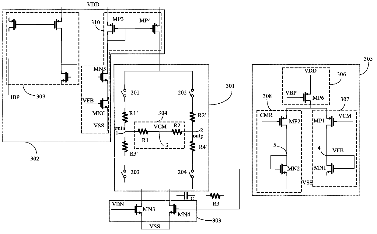
The invention provides a low voltage difference signal LVDS composition circuit comprising the following modules: an LVDS module; a first current mirror module and a second current mirror module; a sampling module used for sampling common mode level outputted by the LVDS module; a feedback control network module used for respectively generating a first feedback signal and a second feedback signal according to the sampled common mode level, respectively sending the first and second feedback signals to the first current mirror module and the second current mirror module, and adjusting output current of the first and second current mirror modules; when the common mode level is higher than a first preset value, the output current of the first current mirror module is reduced and the output current of the second current mirror module are increased; when the common mode level is smaller than a second preset value, the output current of the first current mirror module is increased and the output current of the second current mirror module is reduced; the first preset value is bigger than the second preset value; the LVDS composition circuit can satisfy normal work under high speed state, and adaptation capability of PVT in a large scope.

Description

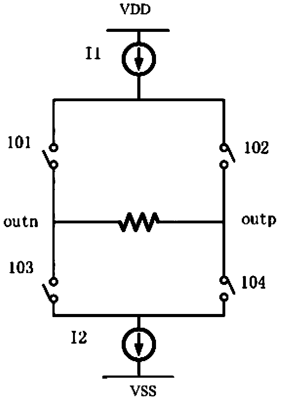
technical field [0001] The invention relates to the technical field of integrated circuits, in particular to a low-voltage differential signal LVDS structure circuit. Background technique [0002] The rapid development of CMOS (Complementary Metal Oxide Semiconductor, Complementary Metal Oxide Semiconductor) integrated circuits makes the transmission data continuously increase and the transmission speed continuously increase. In the past, high-speed data was usually transmitted with a parallel port, but this consumed more area and power consumption. The proposal of the LVDS (Low Voltage Differential Signal) standard provides a fast and low-consumption data transmission method. The field of LVDS design involves the application of low-voltage differential output in high-speed fields. [0003] in, figure 1 It is a schematic diagram of the basic structure of LVDS. In the figure, switches 101, 104 and 102, 103 are turned on alternately, and outp and outn alternately output low ...

Claims


Application Information

Patent Timeline
IPC IPC(8): H03K19/0185
Inventor 李小亮郭先清傅璟军胡文阁
Owner BYD CO LTD
Learn More