Intelligent electrocardiograph monitoring device based on potential and photoelectric detection method

A photoelectric detection and electrocardiographic monitoring technology, which is applied in diagnostic recording/measurement, medical science, sensors, etc., can solve the problem that the reflection path of received light is not unique, it is difficult to convert the relationship between emission and reception, and the accuracy is questionable. , to achieve the effect of convenient calculation of exercise volume, positioning for help, convenient heart rate measurement, and cost reduction

Active Publication Date: 2014-06-25
JIANGSU DATATECH INFORMATION TECH
View PDF6 Cites 22 Cited by
  • Summary
  • Abstract
  • Description
  • Claims
  • Application Information

AI Technical Summary

Problems solved by technology

However, the device must rely on the good contact of more than two electrodes, the tester must operate with both hands, and the test needs to be relatively still to avoid motion interference
In addition, the reflective blood oxygen saturation detection method, because the photoreceiving tube device is located on the same side of the photoelectric emitting device, can only guarantee to receive the light emitted by the photoelectric emitting device on the same side, but the received light of this method is weaker than that of the transmissive type and The reflection path is not unique (in fact, there is diffuse reflection in the human body), so it is difficult to convert the relationship between emission and reception. The accuracy of such a reflective blood oxygen measurement method to measure blood oxygen saturation is still open to question

Method used


Image

  • Intelligent electrocardiograph monitoring device based on potential and photoelectric detection method
  • Intelligent electrocardiograph monitoring device based on potential and photoelectric detection method
  • Intelligent electrocardiograph monitoring device based on potential and photoelectric detection method

Examples


Embodiment Construction

[0013] The present invention will be further described below in conjunction with the accompanying drawings.

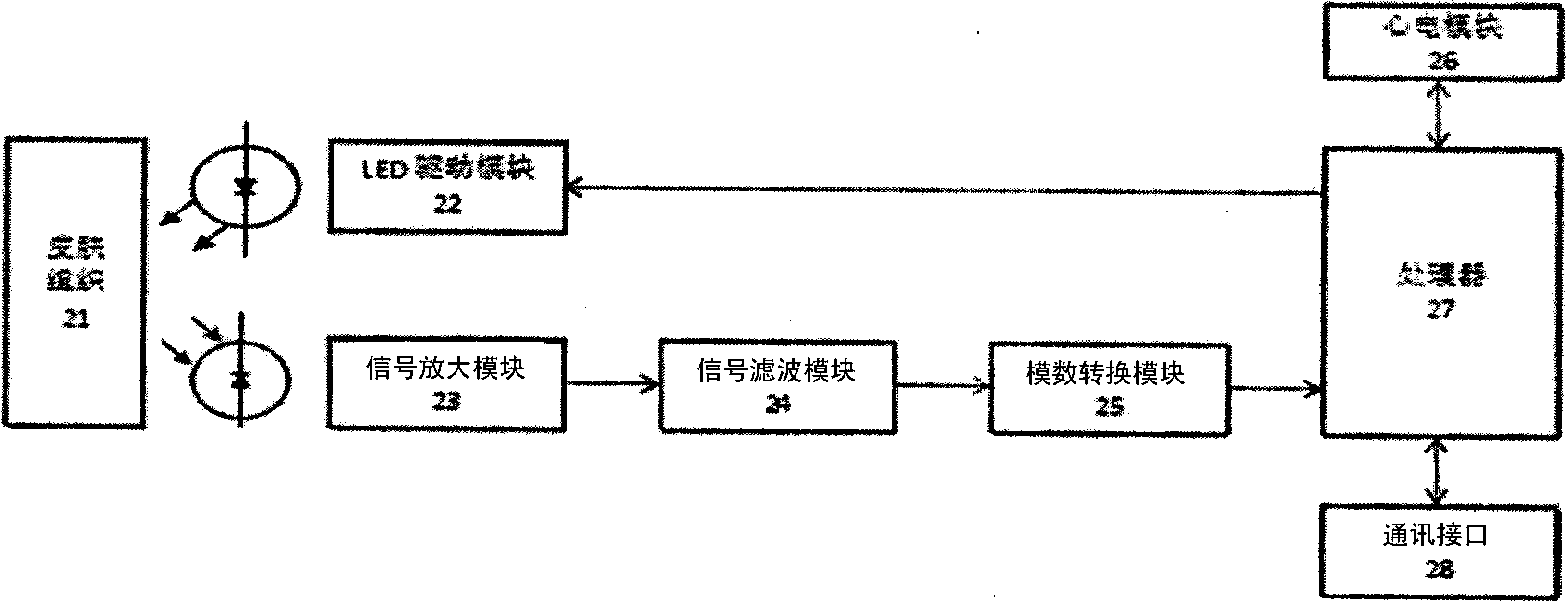
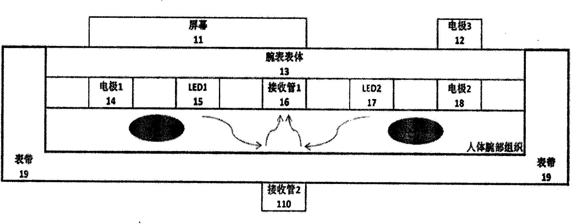
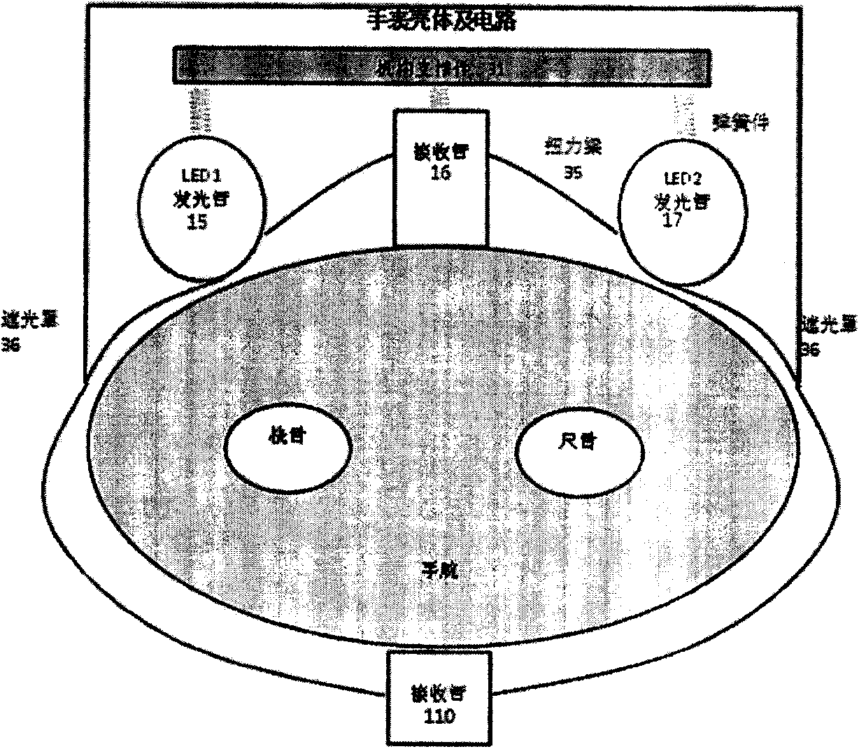
[0014] figure 1 It is a structural diagram of the whole system. This system is a watch-like device. The overall structure includes a screen 11, a watch body 13, a watch strap 19, and sensors (electrodes 12, 14, 18, photoelectric emitting tubes 15, 17, photoelectric receiving tubes 16, 110). For potentiometric measurement, there are 3 electrodes in total. Two electrodes, electrode 1 (14) and electrode 2 (18), are located under the watch, close to the skin, and the other electrode 3 (12) is located on the cover of the watch. One finger press. When the electrode 3 (12) is touched by a finger, the device can automatically sense the finger contact and collect the electrocardiogram. When there is no finger contact, the device automatically switches to photoelectric mode, which can be used when it is inconvenient to operate with both hands, such as sleeping, walking, runni...


PUM


Abstract

The invention discloses an intelligent electrocardiograph monitoring device based on a potential and photoelectric detection method. The intelligent electrocardiograph monitoring device comprises a watch body and a watch cover. Two electrodes are positioned on the lower side of the watch body, and a third electrode positioned on the watch cover needs to be pressed by fingers when in use. When the electrode on the watch cover is touched by the fingers, the device can sense finger touch automatically and collect electrocardiograms. When the electrode on the watch cover is not touched by the fingers, the device is automatically switched into a photoelectric mode to enable a photoelectric driving module to drive a photoelectric emitting tube, a photoelectric receiving tube can transmit received photoelectric signals to a signal amplification module, the signals enter an analog-to-digital conversion module to be converted into digital signals after passing a signal filtering module, and finally, the digital signals are processed by a processor to acquire photoelectric volume tracing waves for heart rate calculation. The intelligent electrocardiograph monitoring device has the greatest advantage that heart rate measurement can be directly completed by a single hand, and can automatically identify connection of electrocardiograph electrodes.

Description

technical field [0001] The invention relates to an intelligent electrocardiographic monitoring device, in particular to an intelligent electrocardiographic monitoring device which combines electrode potential measurement with a photoelectric measurement method. Background technique [0002] The ECG monitoring device in the prior art has dual functions of ECG and blood oxygen detection, and can simultaneously detect blood oxygen and ECG on a wrist watch. The device is portable, easy to use and so on. However, this device must rely on the good contact of two or more electrodes, and the tester must operate with both hands, and it needs to be relatively still during the test to avoid motion interference. In addition, the reflective blood oxygen saturation detection method, because the photoreceiving tube device is located on the same side of the photoelectric emitting device, can only guarantee to receive the light emitted by the photoelectric emitting device on the same side, ...

Claims


Application Information

Patent Timeline
Patent Type & Authority Applications(China)
IPC IPC(8): A61B5/0402A61B5/1455A61B5/0245
Inventor 洪智罗倩倩
Owner JIANGSU DATATECH INFORMATION TECH
Why Eureka
Try Eureka