Parallelism error compensation method and system in magnetic sensor array measurement

A magnetic sensor and error compensation technology, applied in the field of precision magnetic measurement, can solve the problems of small size of magnetic sensor, inability to apply accurate quantitative calculation, large measurement error, etc.

Inactive Publication Date: 2014-06-25
710TH RES INST OF CHINA SHIPBUILDING IND CORP
View PDF9 Cites 19 Cited by
  • Summary
  • Abstract
  • Description
  • Claims
  • Application Information

AI Technical Summary

Problems solved by technology

Theoretical calculations can show that even if the parallelism error between the sensitive axes of each magnetic sensor is only 0.05°, the resulting measurement error can reach tens of nanots, which greatly exceeds the signal strength of the measured target, resulting in The direct consequence is that the measurement error is too large, which cannot be applied to the precise quantitative calculation in the later stage
Due to the small size of the magnetic sens

Method used


Image

  • Parallelism error compensation method and system in magnetic sensor array measurement
  • Parallelism error compensation method and system in magnetic sensor array measurement
  • Parallelism error compensation method and system in magnetic sensor array measurement

Examples


Embodiment Construction

[0030] The present invention will be described in detail below in conjunction with the accompanying drawings.

[0031] A parallelism error compensation method in magnetic sensor array measurement, comprising the following steps:

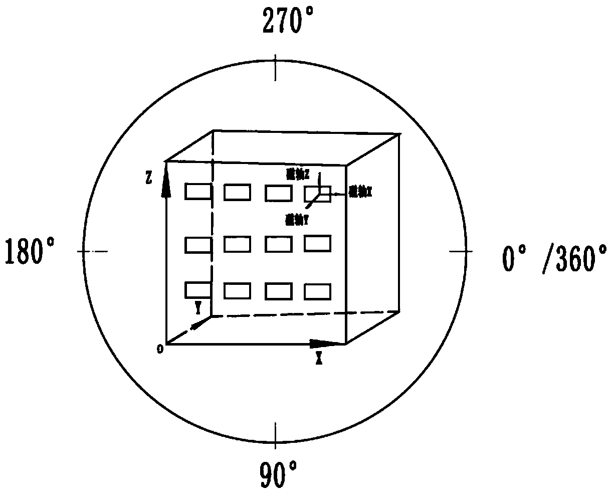
[0032] The magnetic sensor array consists of n three-axis magnetic sensors fixed on the same mounting plate. There are three two-two orthogonal reference lines on the mounting plate, with a vertex as the origin O, and the directions of the three reference lines are X-axis, Y-axis and The coordinate system is established in the direction of the Z axis. Each magnetic sensor has three magnetic axes, which are magnetic axis X, magnetic axis Y, and magnetic axis Z. When forming an array, the magnetic axis X, magnetic axis Y, and magnetic axis Z of each magnetic sensor are parallel to the X of the mounting plate. The reference line of the axis, the reference line of the Y axis, and the reference line of the Z axis are fixed, but there are machining errors...


PUM


Abstract

The invention discloses a parallelism error compensation method and system in magnetic sensor array measurement. A detected magnetic sensor array is fixed to a rotary platform in multiple modes, the magnetic sensor array is rotated, meanwhile, data output by magnetic sensors under different rotating angles are collected, therefore, the fixed azimuth error angles and fixed pitching error angles of magnetic shafts of the magnetic sensors are acquired, a correction matrix is obtained to correct the magnetic sensors, parallelism errors between three-component magnetometer sensitive shafts can be compensated to be within 0.02 degree, and the locating precision of a gradient tensor instrument on a magnetic target is effectively improved.

Description

technical field [0001] The invention relates to the technical field of precision magnetic measurement, in particular to a parallelism error compensation method in magnetic sensor array measurement. Background technique [0002] Gradient tensor detection is a technology that has only been developed in recent years. The magnetic gradient tensor measuring instrument (hereinafter referred to as tensor instrument) composed of multiple vector magnetic sensors can be used to locate magnetic targets. Different from the search positioning method of the optical pump magnetometer, the tensor does not need to search back and forth when locating the magnetic target, and has the advantages of high positioning accuracy and simple operation. [0003] A gradient tensor is a form of magnetic sensor array, which generally consists of several (minimum 3, as many as 9) three-component magnetic sensors. Due to the limitations of the mechanical installation process and the sensor manufacturing pr...

Claims


Application Information

Patent Timeline
IPC IPC(8): G01R33/022G01R35/00
Inventor 李伟陈正想车振孟诚黄捷
Owner 710TH RES INST OF CHINA SHIPBUILDING IND CORP
Why Eureka
Try Eureka